
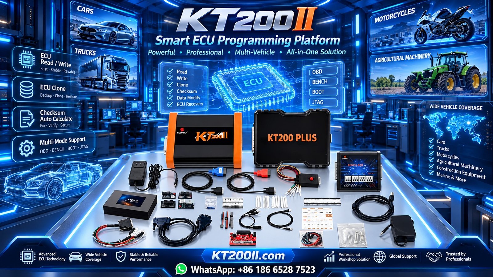
Stable Power Supply for ECU Programming: Voltage, Current and Safety Guide
Stable Power Supply for ECU Programming: Voltage, Current and Safety Guide
A stable power supply is one of the most important requirements when performing automotive ECU programming. Whether technicians are reading Flash memory, writing software, performing EEPROM operations or working with an ECU on the Bench, electrical stability can directly affect the reliability of the programming process.
Insufficient voltage, unstable current delivery, poor ground connections and incorrect wiring can cause communication interruptions or unsuccessful programming operations.
For professional automotive electronics workshops, understanding power supply requirements is essential for protecting both the ECU and programming equipment.
In this KT200II technical guide, we explain how to prepare a suitable power supply, understand voltage and current requirements and avoid common electrical problems during ECU programming.
1. Why Is a Stable Power Supply Important for ECU Programming?
An ECU contains a processor, memory devices, communication circuits and power management components. These electronic circuits require suitable electrical conditions to operate correctly.
During programming, the ECU may perform several operations, including:
- Processor initialization.
- Diagnostic communication.
- Memory identification.
- Flash memory reading.
- Flash memory erasing.
- Flash memory writing.
- Programming verification.
Depending on the controller, certain operations may require stable voltage throughout the entire process.
If the power supply becomes unstable, possible symptoms include:
- ECU communication interruptions.
- Programming errors.
- Unexpected ECU resets.
- Incomplete memory writing.
- Failed identification.
- ECU programming recovery requirements.
Maintaining suitable electrical conditions helps reduce unnecessary programming risks.
2. Understanding Voltage Requirements
Most passenger vehicle electronic systems operate around a nominal 12V electrical architecture, while many commercial vehicles use 24V systems.
However, the actual ECU supply voltage requirements depend on the specific controller and programming procedure.
Technicians should never assume that every ECU requires the same voltage.
Before applying power, verify:
- ECU manufacturer and part number.
- Required operating voltage.
- Power supply terminal locations.
- Ground terminal locations.
- Additional ignition or wake-up requirements.
- Programming equipment instructions.
Some specialized programming procedures may require specific voltage conditions. Always follow the ECU manufacturer's documentation and the programming protocol instructions.
3. Understanding Current Requirements
Voltage and current are two different electrical parameters.
Voltage is the electrical potential supplied to the ECU, while current represents the electrical flow required by the connected electronic system.
An ECU may consume different amounts of current depending on its operating state.
For example:
- Standby operation.
- Processor initialization.
- Communication activity.
- Memory operations.
- Relay and driver activation.
A power supply should have sufficient current capacity for the intended application.
However, selecting a power supply with a higher maximum current rating does not mean the ECU will automatically consume that amount. The ECU draws the current required by its operating conditions, provided the supply is correctly configured.
4. Choosing the Right Power Supply for ECU Programming
A suitable regulated DC power supply is an important tool for professional ECU programming workshops.
When selecting a power supply, consider the following features:
Adjustable Output Voltage
The power supply should allow technicians to configure the output voltage according to the ECU's documented requirements.
Suitable Current Capacity
Choose a unit capable of supplying the current required by the ECU and connected equipment.
Voltage Regulation
A regulated power supply helps maintain a consistent output under changing electrical loads.
Overcurrent Protection
Current protection can help reduce the risk of damage caused by wiring faults or unexpected electrical loads.
Overvoltage Protection
Overvoltage protection helps prevent excessive output voltage from reaching connected electronic equipment.
Display and Monitoring
A clear voltage and current display allows technicians to monitor electrical conditions during programming operations.
5. Battery Charger vs Regulated Power Supply
Many technicians use battery chargers or automotive battery support units during vehicle programming. However, not every charger is suitable for sensitive ECU programming operations.
| Feature | Battery Charger | Regulated DC Supply |
|---|---|---|
| Main purpose | Charging batteries | Providing controlled DC power |
| Voltage regulation | Depends on charger design | Designed for regulated output |
| Current control | Model dependent | Usually configurable |
| Programming suitability | Depends on operating mode | Often suitable when correctly configured |
| Monitoring | Model dependent | Often provides voltage and current readings |
A battery charger should not automatically be treated as a stable programming power supply.
For vehicle-based programming, use an appropriate battery support unit designed for maintaining electrical stability during diagnostic and programming procedures.
For Bench programming, use a regulated supply that meets the specific ECU requirements.
6. How to Prepare the Power Supply Before Bench Programming
Before connecting an ECU to KT200II or another programming tool, technicians should follow a consistent preparation procedure.
- Identify the exact ECU model and hardware reference.
- Obtain the correct ECU wiring diagram.
- Identify all required power and ground terminals.
- Check whether ignition or wake-up signals are necessary.
- Configure the power supply according to the documented voltage requirements.
- Verify the output voltage using the power supply display or a multimeter.
- Check cable condition and connector quality.
- Confirm correct polarity before connecting the ECU.
- Apply power according to the documented connection procedure.
- Monitor voltage and current during the operation.
Never apply power to unidentified ECU terminals.
7. Common Causes of Voltage Drops During ECU Programming
Voltage drops can occur even when the power supply appears to be functioning correctly.
Common causes include:
Undersized Power Cables
Thin cables may introduce excessive resistance, particularly when current demand increases.
Loose Connections
Loose connectors can create unstable electrical contact and intermittent voltage drops.
Corroded Terminals
Oxidation and corrosion can increase electrical resistance at connection points.
Insufficient Power Supply Capacity
A power supply that cannot meet the actual electrical demand may experience voltage instability or current limiting.
Damaged Wiring
Broken conductors or damaged insulation can cause intermittent electrical problems.
Poor Ground Connections
An incorrect or unstable ground connection can affect ECU operation even when the positive supply voltage is correct.
8. How to Monitor Voltage During Flash Writing
Flash writing is an important operation that requires careful preparation.
Before starting a writing operation, technicians should:
- Confirm the ECU programming protocol.
- Verify the required voltage conditions.
- Check the power supply connections.
- Confirm the correct memory file.
- Ensure the computer and programming interface are stable.
- Check that no cables are loose.
During writing, monitor the power supply for unexpected voltage changes or current fluctuations.
Avoid disconnecting the power supply, ECU harness or programming interface while an operation is active.
If an unexpected interruption occurs, follow the programming equipment manufacturer's recovery instructions rather than repeatedly attempting to write the ECU without checking its condition.
9. Why Does an ECU Disconnect During Programming?
Communication interruptions can have several causes, and power instability is only one possibility.
Common causes include:
- Insufficient ECU supply voltage.
- Unstable ground connection.
- Incorrect CAN-H or CAN-L wiring.
- Missing ignition or wake-up signal.
- Damaged communication wiring.
- Incorrect ECU protocol selection.
- Unstable USB connection.
- Programming software or driver problems.
- Internal ECU hardware faults.
Technicians should investigate these possibilities systematically rather than assuming that every communication interruption is caused by the ECU itself.
10. Special Considerations for 24V Commercial Vehicle ECUs
Commercial vehicles, trucks and heavy equipment often use 24V electrical systems.
However, the internal ECU operating voltage may differ from the vehicle's nominal battery system voltage.
Before performing programming operations on commercial vehicle controllers, technicians should verify:
- Vehicle electrical architecture.
- ECU supply voltage requirements.
- Correct connector pinout.
- Required power and ground terminals.
- Additional wake-up signals.
- Supported programming method.
Never apply 24V directly to an ECU simply because the vehicle uses a 24V electrical system. Follow the specific ECU connection documentation.
11. Common Power Supply Mistakes to Avoid
- Using an unsuitable battery charger during programming.
- Applying incorrect voltage to the ECU.
- Ignoring the ECU's current requirements.
- Using damaged or undersized cables.
- Reversing power supply polarity.
- Ignoring ground connections.
- Changing voltage settings during an active operation.
- Disconnecting power during Flash writing.
- Using an unverified wiring diagram.
- Ignoring unexpected current consumption.
Correct electrical preparation is an essential part of professional ECU programming.
12. Using KT200II for ECU Programming
KT200II is an ECU and TCU programming solution designed for automotive electronics technicians and professional repair workshops.
Depending on the exact ECU model, software version and supported programming protocol, available applications may include:
- ECU and TCU identification.
- Supported Flash Read operations.
- Supported Flash Write operations.
- Selected EEPROM operations.
- OBD programming applications.
- Bench programming applications.
- Supported Boot programming applications.
When using KT200II, the power supply and connection method must meet the requirements of the specific ECU protocol.
Before starting a programming operation, technicians should verify ECU compatibility, wiring, electrical stability and original data backup options.
Useful KT200II resources:
- KT200II Official Product Information
- KT200II Operation Modes
- KT200II Software Information
- KT200II Supported ECU List
- KT200II Technical Blog
13. ECU Programming Power Supply Checklist
Use this checklist before starting an ECU programming operation:
- ECU manufacturer and part number identified.
- Required operating voltage confirmed.
- Current capacity checked.
- Regulated power supply selected.
- Correct wiring diagram obtained.
- Power and ground terminals verified.
- Ignition or wake-up requirements checked.
- Power cables inspected.
- Connector polarity confirmed.
- Output voltage measured.
- Programming interface connection checked.
- Original ECU data backed up where supported.
- Power supply monitored during programming.
Frequently Asked Questions
Why is stable voltage important during ECU programming?
ECUs require suitable electrical conditions to maintain processor operation and communication. Voltage instability can interrupt programming and cause unsuccessful memory operations.
Can I use a normal battery charger for ECU programming?
Not every battery charger is suitable. Some chargers have voltage fluctuations or operating modes that are not appropriate for sensitive programming procedures. Use a suitable battery support unit or regulated DC supply.
What voltage should I use for ECU Bench programming?
The correct voltage depends on the exact ECU and programming protocol. Always follow the documented electrical requirements rather than assuming all ECUs use the same voltage.
Does a higher current-rated power supply damage an ECU?
Not simply because its maximum current rating is higher. A correctly configured regulated supply provides the voltage required by the ECU, while the ECU draws current according to its operating conditions. Incorrect voltage or polarity remains dangerous.
Why does voltage drop during ECU programming?
Possible causes include insufficient power supply capacity, undersized cables, loose connections, corroded terminals and poor ground connections.
Can unstable voltage cause Flash writing failure?
Yes. If electrical conditions fall outside the ECU's requirements during programming, communication or memory operations may be interrupted.
Can KT200II work with 24V commercial vehicle ECUs?
Support depends on the exact ECU application and programming protocol. The external power supply requirements must also be verified before connecting the controller.
Should I disconnect the power supply after Flash writing starts?
No. Do not disconnect power during an active writing operation unless the equipment manufacturer's documented recovery procedure specifically requires it.
Conclusion
A stable power supply is essential for reliable automotive ECU programming. Correct voltage, sufficient current capacity, good wiring and reliable ground connections all contribute to successful programming operations.
Before performing Flash reading, Flash writing, EEPROM operations or ECU cloning, technicians should verify the electrical requirements of the exact controller and prepare the programming environment carefully.
Combining correct power supply preparation with compatible programming protocols and appropriate connection methods helps reduce unnecessary failures and improves workshop efficiency.
For more information about ECU programming methods, software and supported applications, visit the KT200II Official Website.