
Diesel ECU Diagnostics Guide: Sensors, Fault Codes, Live Data and Engine Troubleshooting
Diesel ECU Diagnostics Guide: Sensors, Fault Codes, Live Data and Engine Troubleshooting
Modern diesel engines rely on sophisticated electronic control systems to manage fuel injection, turbocharger operation, engine torque and emissions control. These systems depend on accurate sensor information and communication between multiple electronic modules.
When a diesel engine develops a performance problem, electronic diagnostics help technicians identify possible faults and determine whether the problem originates from sensors, wiring, mechanical components, fuel systems or the engine control unit.
For professional diesel repair workshops, understanding ECU diagnostics, diagnostic trouble codes, live data and electronic engine management is essential for efficient troubleshooting.
This guide explains diesel ECU diagnostic principles, common sensors, fault code interpretation, live data analysis, common rail systems and practical troubleshooting procedures.
1. What Is Diesel ECU Diagnostics?
Diesel ECU diagnostics is the process of examining electronic engine control systems to identify faults, monitor operating parameters and evaluate vehicle performance.
The engine control unit receives information from sensors, processes the data and controls different engine components.
Diagnostic equipment allows technicians to communicate with supported electronic controllers and retrieve useful information.
Depending on the vehicle and diagnostic system, available information may include:
- ECU identification.
- Diagnostic trouble codes.
- Live engine data.
- Sensor readings.
- Fuel pressure information.
- Engine speed and load.
- Boost pressure information.
- Temperature readings.
- Selected adaptation information.
2. Understanding the Diesel Engine Control Unit
The diesel engine control unit, commonly called the ECM or ECU, is responsible for managing electronic engine operation.
Depending on the engine configuration, its functions may include:
- Fuel injection quantity calculation.
- Injection timing control.
- Common rail pressure regulation.
- Turbocharger boost management.
- Engine torque management.
- Exhaust gas recirculation control.
- Diesel particulate filter monitoring.
- Selective catalytic reduction management where equipped.
- Engine protection strategies.
The ECU continuously processes sensor information to maintain appropriate engine operation under different driving conditions.
3. Understanding Diesel Engine Sensors
Diesel engine management depends on information from multiple sensors.
These sensors provide the ECU with information about engine conditions, air intake, fuel pressure and exhaust operation.
Common diesel engine sensors include:
- Crankshaft position sensor.
- Camshaft position sensor.
- Engine coolant temperature sensor.
- Intake air temperature sensor.
- Mass airflow sensor.
- Manifold absolute pressure sensor.
- Fuel rail pressure sensor.
- Accelerator pedal position sensor.
- Exhaust gas temperature sensor.
- NOx sensor where equipped.
- DPF differential pressure sensor.
A faulty sensor, damaged connector or wiring problem can cause incorrect engine operating information.
4. Understanding Crankshaft and Camshaft Sensors
Crankshaft and camshaft position sensors provide important information for diesel engine synchronization.
Crankshaft Position Sensor
The crankshaft sensor provides information about engine speed and crankshaft position.
The ECU uses this information to calculate injection timing and coordinate engine operation.
Camshaft Position Sensor
The camshaft sensor provides information about camshaft position and engine phase.
It helps the ECU determine the correct synchronization between the engine's mechanical components and electronic fuel injection system.
Faults in these sensors or their circuits may result in starting difficulties, unstable operation or engine synchronization errors.
5. Understanding Common Rail Fuel Pressure
Common rail fuel injection is widely used in modern diesel engines.
The system maintains high-pressure fuel in a shared rail and electronically controls fuel delivery through individual injectors.
Important components include:
- High-pressure fuel pump.
- Common rail accumulator.
- Fuel rail pressure sensor.
- Fuel metering valve.
- Pressure regulation components.
- Electronic injectors.
The ECU compares requested and measured fuel pressure to coordinate fuel system operation.
Abnormal rail pressure readings may result from fuel supply restrictions, pump problems, sensor faults, wiring issues or pressure regulation problems.
6. Understanding Turbocharger Boost Pressure
Many modern diesel engines use turbochargers to improve engine performance and efficiency.
The ECU may monitor and control boost pressure through different sensors and actuator systems.
Depending on the engine configuration, relevant components may include:
- Manifold absolute pressure sensor.
- Mass airflow sensor.
- Turbocharger actuator.
- Variable geometry turbocharger mechanism.
- Boost pressure control solenoid.
- Intake air temperature sensor.
Comparing requested boost pressure with measured boost pressure can help technicians investigate performance problems.
7. What Are Diagnostic Trouble Codes?
Diagnostic Trouble Codes, commonly called DTCs, are codes stored by electronic control units when monitored operating conditions indicate a possible fault.
Diagnostic codes help technicians identify the system or circuit requiring further investigation.
Depending on the vehicle, diagnostic information may include:
- Fault code number.
- Fault description.
- Current or stored status.
- Freeze-frame information where supported.
- Related operating conditions.
A diagnostic trouble code identifies a detected condition, not necessarily the exact failed component.
For example, a pressure sensor-related code may originate from the sensor, wiring, connector, power supply or an actual pressure problem.
8. Understanding Current, Pending and Stored Fault Codes
Diagnostic systems may classify faults according to their detection status.
Current Fault Codes
These indicate faults currently detected by the control unit under the applicable monitoring conditions.
Pending Fault Codes
These indicate conditions that have been detected but may not yet meet all requirements for confirmed fault registration.
Stored or Historical Fault Codes
These indicate faults previously detected and retained in controller memory.
Technicians should review fault status and operating conditions before deciding whether a component requires replacement.
9. Understanding Live Data in Diesel ECU Diagnostics
Live data provides information about current engine operating conditions as reported by the ECU.
Depending on the vehicle and diagnostic equipment, available parameters may include:
- Engine speed.
- Coolant temperature.
- Fuel rail pressure.
- Requested fuel pressure.
- Measured fuel pressure.
- Airflow readings.
- Intake manifold pressure.
- Turbocharger boost pressure.
- Accelerator pedal position.
- Injection quantity.
- Exhaust temperature.
Live data is particularly useful when a fault occurs intermittently or when a technician needs to compare requested values with measured values.
10. How to Analyze Diesel ECU Live Data
Correct live data analysis requires understanding the operating conditions under which the values were recorded.
A practical diagnostic process includes:
Step 1: Record Engine Conditions
Record whether the engine is stopped, idling, operating under load or running at a specific engine speed.
Step 2: Check Sensor Values
Compare sensor readings with expected values for the specific engine and operating conditions.
Step 3: Compare Requested and Actual Values
Where supported, compare requested fuel pressure, boost pressure and other controlled parameters with measured values.
Step 4: Investigate Abnormal Readings
Inspect the related sensor, wiring, connectors and mechanical components.
Step 5: Confirm the Repair
Repeat the diagnostic procedure under appropriate conditions to verify whether the original problem has been resolved.
11. Common Diesel Engine Diagnostic Problems
Diesel engine faults may originate from electronic, mechanical, fuel system or emissions-related problems.
Common symptoms include:
- Engine fails to start.
- Difficulty starting when cold.
- Loss of engine power.
- Unstable idle.
- Excessive fuel consumption.
- Abnormal exhaust smoke.
- Turbocharger performance problems.
- Fuel pressure faults.
- DPF warning messages.
- Engine warning lights.
- ECU communication problems.
These symptoms do not automatically indicate an ECU failure.
Technicians should investigate the complete engine management system before replacing electronic components.
12. Diagnosing Diesel Engine Starting Problems
Starting problems can result from several mechanical and electronic conditions.
Important diagnostic checks include:
- Battery voltage.
- Starter motor operation.
- Crankshaft sensor signal.
- Camshaft sensor signal.
- Fuel supply pressure.
- Common rail pressure during cranking.
- Injector operation.
- Immobilizer authorization where applicable.
- ECU power and ground connections.
Live data and fault code analysis can help narrow down the possible causes.
13. Diagnosing Diesel Engine Power Loss
Loss of engine power is a common complaint in commercial vehicle and passenger diesel repair workshops.
Possible causes include:
- Insufficient fuel supply.
- Abnormal rail pressure.
- Air intake restrictions.
- Boost pressure problems.
- Turbocharger actuator faults.
- Airflow sensor problems.
- Exhaust restrictions.
- DPF-related faults.
- Engine protection strategies.
Comparing live data with the applicable manufacturer specifications helps technicians identify the area requiring further inspection.
14. Diagnosing DPF and SCR-Related Problems
Modern diesel vehicles may use several aftertreatment technologies to reduce exhaust emissions.
Depending on the vehicle generation, these systems may include:
- Diesel Particulate Filter.
- Selective Catalytic Reduction.
- Diesel Exhaust Fluid system.
- Exhaust temperature sensors.
- NOx sensors.
- DPF differential pressure sensors.
Diagnostic checks should include relevant sensor readings, system status, wiring and physical component condition.
Aftertreatment systems must be diagnosed and repaired in accordance with applicable emissions regulations.
15. Understanding ECU Communication Problems
Communication problems can prevent diagnostic equipment from accessing the engine controller.
Possible causes include:
- Insufficient battery voltage.
- Missing ECU power supply.
- Poor ground connections.
- Damaged diagnostic connector.
- CAN communication wiring faults.
- Gateway or network problems.
- Incorrect diagnostic interface selection.
- Internal ECU hardware failure.
Technicians should inspect external electrical conditions before concluding that the ECU itself is defective.
16. ECU Diagnostics vs. ECU Programming
Diagnostics and programming are related but different automotive electronics operations.
| Function | Purpose |
|---|---|
| ECU Diagnostics | Identify faults and monitor controller information |
| Live Data | Monitor real-time operating parameters |
| Flash Reading | Retrieve supported ECU memory data |
| Flash Writing | Program compatible ECU software or calibration data |
| ECU Cloning | Transfer supported memory data to compatible replacement hardware |
Not every ECU programmer provides comprehensive vehicle diagnostics. Always check the actual functions of the selected equipment.
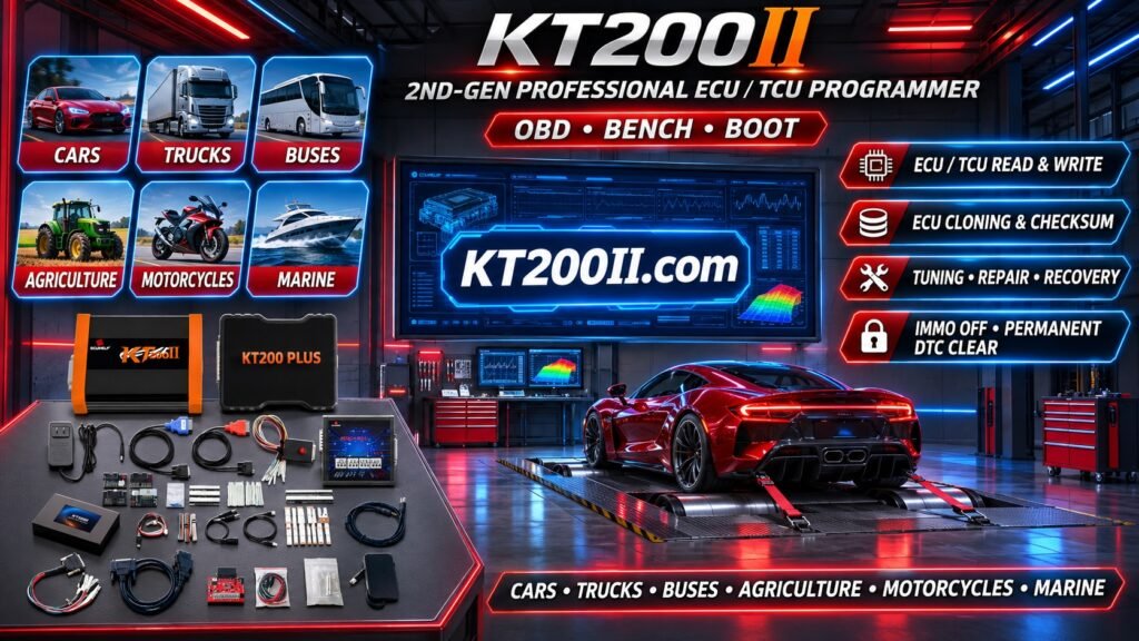
17. Using KT200II for ECU Programming Workflows
KT200II is designed for professional automotive electronics programming applications.
Depending on the selected protocol and supported ECU hardware, available programming workflows may include:
- ECU identification.
- Supported ECU reading.
- Supported ECU writing.
- Flash memory operations.
- Selected memory operations.
- Supported OBD programming.
- Supported Bench programming.
- Supported Boot operations.
- Original data backup where supported.
KT200II programming functions should not be confused with a universal truck diagnostic scanner. Fault code reading, live data and other diagnostic functions depend on the diagnostic equipment and software being used.
For KT200II product and technical information, visit:
- KT200II Product Information
- KT200II Operation Modes
- KT200II Software Information
- KT200II Support List
18. Best Practices for Professional Diesel Diagnostics
Professional technicians should follow a systematic diagnostic process.
- Record vehicle and engine identification.
- Identify the engine ECU hardware number.
- Read and document all relevant fault codes.
- Review fault status and freeze-frame data where available.
- Monitor relevant live data.
- Compare requested and measured parameters.
- Inspect sensors and wiring.
- Check fuel system operation.
- Inspect turbocharger and air intake components.
- Evaluate emissions system condition.
- Verify repairs through follow-up diagnostics.
19. Diesel ECU Diagnostic Checklist
Before completing a diesel engine diagnostic job, confirm:
- Vehicle manufacturer and model recorded.
- Engine model identified.
- ECU manufacturer and hardware number recorded.
- Diagnostic communication established.
- Fault codes retrieved.
- Current and historical faults distinguished.
- Relevant live data recorded.
- Fuel pressure checked.
- Airflow and boost readings checked.
- Sensor and wiring conditions inspected.
- Emissions system faults evaluated.
- Repair results verified.
Frequently Asked Questions
What is diesel ECU diagnostics?
It is the process of examining the diesel engine control system using diagnostic equipment to identify faults, retrieve operating information and evaluate engine performance.
What is the difference between ECU fault codes and live data?
Fault codes identify detected abnormal conditions, while live data displays operating information reported by the ECU.
Can a sensor fault cause diesel engine power loss?
Yes. Incorrect sensor information can affect fuel injection, boost control and engine protection strategies.
Does an ECU fault code always mean the ECU is damaged?
No. A fault code may relate to an external sensor, wiring circuit, actuator, fuel system or mechanical component.
Can KT200II read diesel engine fault codes?
KT200II is primarily an ECU programming tool. Its programming capabilities should not be confused with comprehensive diagnostic scanner functions. Use compatible diagnostic equipment for fault code and live data analysis.
Can ECU programming fix diesel engine problems?
Programming can address certain supported software-related issues, but it cannot repair damaged injectors, fuel pumps, sensors, turbochargers or other mechanical components.
Why is comparing requested and actual live data important?
It helps technicians identify whether a controlled system is responding as expected and provides useful information for further troubleshooting.
Conclusion
Diesel ECU diagnostics is an essential part of modern diesel engine maintenance and electronic troubleshooting.
Understanding sensor signals, diagnostic trouble codes, live data, common rail fuel systems and emissions control technologies helps technicians identify problems more accurately.
Accurate diagnosis should combine electronic information with electrical testing and mechanical inspection rather than relying on fault codes alone.
KT200II provides ECU programming solutions for professional automotive electronics applications, with available functions depending on the selected protocol and supported controller.
Visit KT200II.com to explore product information, operation modes, software resources and supported ECU protocols.