
ECU Flash Reading and Writing Guide: Original Data Backup and Software Programming
ECU Flash Reading and Writing Guide: Original Data Backup and Software Programming
ECU Flash reading and writing are fundamental operations in modern automotive electronics programming. Professional technicians use these functions to retrieve original controller software, create backups, perform supported software updates and restore compatible ECU data.
Modern engine control units contain complex embedded software and calibration information. Understanding how Flash memory works, how ECU data is organized and how programming protocols communicate with controllers is essential for safe and reliable operations.
This guide explains ECU Flash memory, original data backup, reading and writing procedures, OBD and Bench programming, Boot access, checksum verification and common programming problems.
1. What Is ECU Flash Memory?
Flash memory is a type of non-volatile electronic memory used in automotive control units to store software and calibration information.
Unlike temporary memory, Flash retains stored information when electrical power is disconnected.
Depending on the ECU architecture, Flash memory may contain:
- Engine management application software.
- Fuel injection control strategies.
- Ignition timing maps.
- Engine torque management parameters.
- Turbocharger boost control calibration.
- Air intake management strategies.
- Transmission control software.
- Emissions management functions.
- Diagnostic routines.
The exact memory organization varies according to the ECU manufacturer, processor and hardware generation.
2. What Is ECU Flash Reading?
ECU Flash reading is the process of retrieving supported software and calibration data from an electronic control unit using compatible programming equipment.
The retrieved data can be saved as a file for backup, technical analysis or compatible programming operations.
Depending on the controller and programming protocol, reading operations may include:
- Complete supported Flash reading.
- Application software reading.
- Calibration data reading.
- Selected memory region reading.
- Original software backup.
Not every ECU supports complete memory reading through every connection method.
3. What Is ECU Flash Writing?
ECU Flash writing transfers compatible software or calibration data into the controller's supported memory regions.
Depending on the ECU and available programming protocol, writing operations may include:
- Original software restoration.
- Supported software updates.
- Compatible calibration updates.
- Selected Flash memory programming.
- Software replacement procedures.
Before writing data, technicians must verify that the target file matches the ECU hardware, software architecture and memory structure.
An incorrect file or interrupted programming operation may cause the ECU to stop communicating or become inoperative.
4. ECU Flash Reading vs. Flash Writing
Although reading and writing are closely related, they are separate programming capabilities.
| Operation | Purpose | Result |
|---|---|---|
| Flash Reading | Retrieve supported ECU memory data | Saved software file |
| Flash Writing | Program compatible data into ECU memory | Updated or restored memory |
| Data Backup | Preserve original controller information | Backup file |
| Data Restoration | Restore compatible original information | Recovered ECU data |
Successful Flash reading does not automatically guarantee Flash writing support. Both operations must be verified for the exact ECU protocol.
5. Understanding Original ECU Data Backup
Creating an original data backup is an important preparation step before performing supported programming operations.
An original backup provides a reference copy of the controller's available memory data.
Depending on the ECU architecture, the backup may contain:
- Original application software.
- Calibration information.
- Supported persistent memory data.
- Controller configuration information.
- Selected manufacturer-specific data.
Technicians should save backup files using clear identification information, including the ECU manufacturer, hardware number, software version and reading date.
6. Understanding ECU Flash Memory Types
Different automotive controllers use different memory architectures.
Internal Flash
Internal Flash is integrated into the microcontroller. It may store application software and other controller information.
External Flash
Some ECUs use separate Flash memory components connected to the main processor.
Calibration Memory
Calibration information contains parameters used by the ECU to control engine or transmission operation.
These memory areas may be organized differently depending on the controller design. Technicians should not assume that every ECU has the same memory structure.
7. Flash Memory vs. EEPROM
Flash and EEPROM are both non-volatile memory technologies, but they may serve different purposes within an automotive controller.
| Feature | Flash Memory | EEPROM |
|---|---|---|
| Memory Type | Non-volatile | Non-volatile |
| Typical Use | Application software and calibration | Configuration and persistent information |
| Organization | Sector or block based | Byte or page based, depending on technology |
| Implementation | Internal or external | Separate chip or integrated memory |
Some modern controllers use integrated Data Flash instead of a separate EEPROM chip.
Always identify the actual memory architecture before selecting a reading or writing operation.
8. OBD Flash Reading and Writing
OBD programming communicates with supported ECUs through the vehicle diagnostic connector.
Depending on the controller and available protocol, OBD operations may include:
- ECU identification.
- Software identification.
- Supported Flash reading.
- Supported Flash writing.
- Selected diagnostic operations.
One advantage of OBD programming is that the ECU generally remains installed in the vehicle.
However, complete Flash access is not available through OBD for every controller.
9. Bench Flash Reading and Writing
Bench programming establishes a direct connection to a removed ECU using supported external electrical connections.
Depending on the controller hardware, the connection may require:
- Battery positive.
- Ignition-switched power.
- Ground.
- CAN-H.
- CAN-L.
- Additional activation signals where required.
Bench programming may support ECU identification, Flash reading and writing, depending on the selected protocol.
The correct wiring diagram must always be checked against the complete ECU hardware number.
10. Boot Mode Flash Programming
Boot programming provides supported low-level access to selected automotive microcontrollers.
Depending on the processor and programming protocol, available operations may include:
- Processor identification.
- Supported Flash reading.
- Supported Flash writing.
- Selected memory operations.
- Specific software recovery procedures.
Boot access requirements differ between processor architectures and ECU generations.
Not every controller supports the same Boot programming procedure.
11. Why ECU Identification Matters Before Flash Programming
One of the most important steps before reading or writing ECU data is accurate controller identification.
Technicians should record:
- ECU manufacturer.
- Complete hardware number.
- Controller designation.
- Hardware revision.
- Software identification.
- Processor model where available.
- Vehicle manufacturer.
- Engine application.
Two ECUs from the same controller family may have different hardware revisions, memory configurations or software requirements.
For example, identifying a controller only as Bosch EDC17 is not sufficient to establish complete programming compatibility.
12. Understanding ECU Software Compatibility
Software compatibility is essential when writing Flash data into an ECU.
A target file should be evaluated against:
- ECU hardware number.
- Processor architecture.
- Memory configuration.
- Original software version.
- Vehicle application.
- Calibration compatibility.
- Supported programming protocol.
Using an incompatible file may result in programming errors, communication problems or incorrect vehicle operation.
13. Understanding Checksum Verification
Checksum verification helps maintain data integrity during supported ECU programming operations.
Depending on the software architecture, checksum calculations may apply to selected memory regions or calibration blocks.
Important considerations include:
- Correct ECU identification.
- Compatible software files.
- Supported checksum algorithms.
- Correct memory structure.
- Final file verification.
Checksum requirements vary between ECU manufacturers, hardware generations and software versions.
14. Common Problems During ECU Flash Reading
Flash reading operations may fail for several reasons.
Common problems include:
- Incorrect ECU identification.
- Unsupported programming protocol.
- Incorrect wiring connections.
- Unstable electrical power.
- Communication interruption.
- Processor access restrictions.
- Unsupported hardware revision.
Before repeating a reading operation, verify the wiring, power supply and selected protocol.
15. Common Problems During ECU Flash Writing
Flash writing requires particular care because an interrupted or incompatible programming operation can affect ECU operation.
Common problems include:
- Incompatible target file.
- Incorrect memory selection.
- Unsupported writing protocol.
- Unstable power supply.
- Communication interruption.
- Checksum errors.
- Hardware protection restrictions.
Technicians should verify the original backup, target file and programming requirements before starting a writing operation.
16. How to Perform a Safe ECU Flash Programming Workflow
A systematic workflow helps reduce programming risks.
Step 1: Identify the ECU
Record the complete hardware number, controller designation and software identification.
Step 2: Confirm Protocol Compatibility
Verify that the selected ECU programmer supports the exact controller and required reading or writing operation.
Step 3: Select the Correct Connection Method
Determine whether OBD, Bench or Boot programming is supported.
Step 4: Check Electrical Connections
Verify power, ground and communication connections using the correct wiring documentation.
Step 5: Read and Back Up Original Data
Where supported, save the original ECU memory data before making changes.
Step 6: Verify the Target File
Confirm hardware and software compatibility before writing any data.
Step 7: Perform the Programming Operation
Follow the programming software instructions and maintain stable electrical power throughout the operation.
Step 8: Verify the Result
Check ECU identification, communication and relevant vehicle diagnostic functions after programming.
17. ECU Flash Programming Safety Recommendations
Professional technicians should follow these recommendations:
- Always record the original ECU identification.
- Back up supported original memory before programming.
- Use compatible software files.
- Verify the correct memory structure.
- Use the appropriate regulated power supply.
- Maintain stable voltage during writing.
- Avoid disconnecting communication cables during programming.
- Follow the supported programming procedure.
- Verify checksum requirements.
- Perform final diagnostic checks.
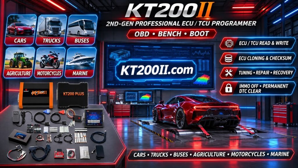
18. Using KT200II for Supported ECU Flash Operations
KT200II is an ECU programming tool designed for professional automotive electronics applications.
Depending on the selected programming protocol and supported controller, KT200II may provide different ECU memory operations, including:
- ECU identification.
- Supported Flash reading.
- Supported Flash writing.
- Selected memory operations.
- Original data backup where supported.
- Supported OBD programming.
- Supported Bench programming.
- Supported Boot operations.
Actual functionality depends on the ECU manufacturer, complete hardware number, processor architecture, memory configuration and software version.
Reading support and writing support should always be checked separately.
For detailed technical information, visit the official resources:
- KT200II Product Information
- KT200II Operation Modes
- KT200II Software Information
- KT200II Support List
19. ECU Flash Programming Checklist
Before starting a Flash reading or writing operation, confirm:
- Vehicle identification recorded.
- ECU manufacturer identified.
- Complete hardware number recorded.
- Software identification checked.
- Processor architecture identified where necessary.
- Memory configuration understood.
- Reading and writing compatibility verified.
- OBD, Bench or Boot method selected.
- Correct wiring diagram obtained.
- Power supply stability confirmed.
- Original data backed up where supported.
- Target file compatibility verified.
- Checksum requirements checked.
- Final ECU diagnostics performed.
Frequently Asked Questions
What is ECU Flash reading?
ECU Flash reading retrieves supported software and calibration information from an electronic control unit and saves it as a file.
What is ECU Flash writing?
ECU Flash writing transfers compatible software or calibration data into supported ECU memory regions.
Does every ECU support complete Flash reading?
No. Memory access depends on the controller hardware, processor, security configuration and programming protocol.
Does reading an ECU guarantee writing support?
No. Reading and writing are separate capabilities and must be verified individually.
What is the difference between Flash and EEPROM?
Flash commonly stores application software and calibration information, while EEPROM or other persistent memory technologies may store configuration and other retained information.
Can ECU Flash data be used for cloning?
Selected controllers support memory backup and transfer to compatible replacement hardware. Additional persistent memory or configuration operations may also be required.
Why does ECU Flash writing fail?
Possible causes include incompatible software, unsupported protocols, unstable power, communication interruption, checksum errors or hardware protection restrictions.
Should I always back up original ECU data?
Yes, whenever supported. Original backups provide an important reference for compatible restoration and repair procedures.
Conclusion
ECU Flash reading and writing are fundamental operations in professional automotive electronics programming.
Understanding Flash memory, software compatibility, original data backup, checksum verification and supported programming methods helps technicians perform more reliable ECU operations.
Successful programming requires accurate controller identification, compatible equipment, correct wiring, stable electrical power and careful verification.
KT200II provides ECU programming solutions for professional automotive electronics applications, with available functions depending on the selected protocol and supported controller.
Visit KT200II.com to explore product information, operation modes, software resources and supported ECU protocols.