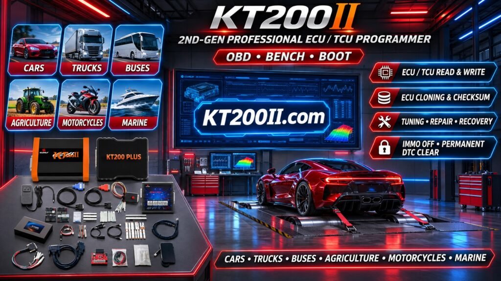

ECU Bench Programming Explained: Connections, Procedures and Troubleshooting
ECU Bench Programming Explained: Connections, Procedures and Troubleshooting
ECU Bench programming is an important technique in modern automotive electronics repair. It allows technicians to communicate with supported engine control units directly outside the vehicle without relying on the vehicle's diagnostic connector.
This method is widely used for ECU identification, memory backup, software programming, controller replacement and selected cloning applications.
Unlike OBD programming, which communicates through the vehicle diagnostic network, Bench programming requires direct electrical connections to the ECU.
Understanding power supply requirements, communication wiring, programming protocols and memory architecture is essential for safe and reliable operation.
In this guide, we explain how ECU Bench programming works, how to prepare the connections, what programming operations may be available and how KT200II can assist with supported applications.
1. What Is ECU Bench Programming?
ECU Bench programming is a method of accessing an automotive electronic control unit outside the vehicle.
The ECU is removed from the vehicle and connected directly to a programming tool using the documented electrical terminals.
Depending on the ECU and supported protocol, Bench programming may provide access to:
- ECU identification.
- Flash memory reading.
- Flash memory writing.
- Selected EEPROM operations.
- Software backup.
- Supported ECU replacement procedures.
- Selected cloning-related operations.
Not every ECU supports all these functions through Bench mode. Available operations depend on the controller hardware and programming protocol.
2. ECU Bench Programming vs OBD and Boot Mode
OBD, Bench and Boot are different ECU access methods. Choosing the correct method depends on the ECU architecture and the intended operation.
| Feature | OBD | Bench | Boot |
|---|---|---|---|
| Connection | Vehicle diagnostic connector | Direct ECU connections | Supported processor-level connections |
| ECU Removal | Usually unnecessary | Usually required | Usually required |
| Communication | Vehicle diagnostic network | Documented ECU interfaces | Boot communication interface |
| Memory Access | Protocol-dependent | Protocol-dependent | Processor-dependent |
| Typical Applications | Supported vehicle programming | Direct ECU programming | Supported low-level access |
Bench mode should not be confused with Boot mode. A Bench connection does not automatically provide processor-level Boot access.
3. What Equipment Is Needed for ECU Bench Programming?
A typical Bench programming workstation includes several essential components.
ECU Programmer
A compatible ECU programmer provides communication and supported memory operations.
The programmer must support the exact ECU and selected programming protocol.
Bench Cable and Adapters
Appropriate cables and adapters connect the programmer to the ECU terminals.
Different ECU manufacturers and hardware generations may require different connection arrangements.
Regulated Power Supply
A stable power source is required to provide the electrical supply specified for the ECU.
The voltage and current capacity must meet the controller's documented requirements.
Connection Diagram
A reliable wiring diagram is essential for identifying the correct power, ground and communication terminals.
Computer and Programming Software
The computer runs the programming software, displays identification information and manages supported reading and writing operations.
4. Understanding ECU Power and Ground Connections
Correct electrical connections are essential for successful Bench programming.
Depending on the ECU architecture, the required connections may include:
- Permanent battery power.
- Ignition or wake-up signal.
- Ground connections.
- CAN communication lines.
- Other protocol-specific connections.
Power Supply
The ECU must receive the correct supply voltage according to its technical documentation.
Insufficient voltage can prevent initialization or cause communication instability.
Ground
Ground connections provide the electrical reference required for the ECU and programming interface.
Poor grounding can cause communication failures or unexpected programming interruptions.
Ignition and Wake-Up Signals
Some ECUs require an ignition or wake-up signal before they can establish communication.
Other controllers use different activation procedures.
Never assume that all ECUs use the same power-up sequence.
5. Understanding CAN-H and CAN-L
CAN Bus is widely used for communication between automotive electronic control modules.
Many Bench programming procedures use CAN communication when supported by the ECU.
CAN-H
CAN-H is the high-side signal line of the Controller Area Network.
CAN-L
CAN-L is the low-side signal line.
The two communication lines work together to transmit differential signals.
Important considerations include:
- Verify CAN-H and CAN-L using the exact wiring diagram.
- Check connector pin assignments carefully.
- Inspect cables and terminal contacts.
- Check for short circuits.
- Confirm that the selected protocol uses the expected communication interface.
Not every ECU uses the same communication pins or CAN configuration. Some controllers use other interfaces or additional communication lines.
6. How to Prepare an ECU for Bench Programming
Before connecting the ECU to a programmer, technicians should complete several preparation steps.
Step 1: Identify the ECU
Record the manufacturer, complete part number, hardware number and software identification where available.
Step 2: Confirm Protocol Support
Check whether the exact ECU is supported for Bench programming and identify which operations are available.
Step 3: Locate the Correct Wiring Diagram
Use the connection documentation for the specific ECU hardware version.
Step 4: Inspect the ECU
Check the housing, connectors and circuit board for visible damage where inspection is appropriate.
Step 5: Prepare the Power Supply
Set up a regulated power supply according to the ECU's documented electrical requirements.
Step 6: Verify All Connections
Double-check power, ground, ignition and communication connections before applying power.
Step 7: Connect the Programmer
Connect the appropriate programming cable and follow the software instructions for the selected protocol.
7. Reading ECU Data in Bench Mode
One of the most common reasons for using Bench programming is to read original ECU memory data.
Depending on the supported protocol, available reading functions may include:
- ECU identification.
- Flash memory reading.
- Selected EEPROM reading.
- Other supported memory operations.
Before reading, technicians should confirm the expected memory regions and file sizes.
After reading:
- Save the original files.
- Keep the original backup unchanged.
- Record the ECU identification information.
- Verify the file format and size.
- Store backup files in an organized location.
Remember that reading one memory region does not necessarily create a complete ECU backup.
8. Writing ECU Data in Bench Mode
Bench programming may also provide supported memory writing functions.
Before writing any file, verify:
- Correct ECU part number.
- Hardware compatibility.
- Software compatibility.
- File format and size.
- Required checksum or integrity correction.
- Correct programming protocol.
- Stable power supply.
Never assume that a file from a similar ECU is suitable for the target controller.
Incorrect memory data may cause communication failure, controller malfunction or unsuccessful startup.
9. Flash and EEPROM Operations During Bench Programming
Different ECU architectures use different memory arrangements.
Flash Memory
Flash commonly stores the application software and calibration data used by the ECU.
Depending on the controller, supported Bench operations may include reading and writing selected Flash regions.
EEPROM
EEPROM or EEPROM-emulated memory may contain persistent configuration and controller-specific information.
Some ECUs use separate EEPROM chips, while others integrate persistent storage into the microcontroller.
Separate EEPROM reading or writing is therefore not available on every controller.
10. Common Problems During ECU Bench Programming
ECU Cannot Be Identified
Possible causes include incorrect power connections, missing wake-up signals, communication wiring problems or an unsupported protocol.
Programmer Does Not Establish Communication
Check the selected protocol, power supply, grounding and communication connections.
CAN Communication Failure
Verify CAN-H and CAN-L against the correct wiring diagram. Inspect connectors and cable continuity.
Flash Reading Fails
The selected protocol may not support the requested memory operation, or the ECU may have a hardware problem.
Flash Writing Is Interrupted
Power instability, loose connections or communication interruptions can affect programming.
ECU Is Recognized but Writing Is Unavailable
Identification support does not automatically mean that Flash writing or EEPROM access is supported.
Check the actual functions listed in the selected protocol.
11. Bench Programming and ECU Cloning
Bench programming is frequently used in supported ECU cloning and replacement workflows.
When an original ECU needs replacement, technicians may use Bench mode to access the required memory regions.
A typical workflow may involve:
- Identifying the original ECU.
- Checking donor ECU compatibility.
- Reading required original memory data.
- Saving Flash and persistent memory backups where supported.
- Verifying file compatibility.
- Writing the required data to the donor ECU.
- Performing post-programming checks.
Not every ECU can be cloned using Bench programming alone. Some controllers require Boot access, additional configuration or manufacturer-specific adaptation.
12. How KT200II Supports ECU Bench Programming
KT200II is a professional ECU and TCU programming solution designed for automotive electronics technicians and repair workshops.
For supported ECU applications, KT200II provides Bench programming functions that may include:
- ECU identification.
- Supported Flash reading.
- Supported Flash writing.
- Selected EEPROM operations.
- Supported ECU backup operations.
- Selected ECU replacement and cloning-related functions.
Available functions depend on the exact ECU, processor, hardware version and selected software protocol.
KT200II should always be used with the correct connection diagram and supported programming procedure.
Explore more information:
KT200II Supported ECU and TCU List
13. Best Practices for Safe Bench Programming
Professional technicians should follow consistent procedures to reduce the risk of programming failure.
- Identify the ECU before connecting the programmer.
- Use the correct wiring diagram.
- Verify all power and ground connections.
- Check CAN wiring where applicable.
- Use a stable regulated power supply.
- Confirm protocol compatibility.
- Back up original data where supported.
- Keep original and modified files separate.
- Avoid disconnecting cables during active programming.
- Verify programming results.
- Perform post-programming diagnostics.
14. ECU Bench Programming Checklist
Use this checklist before beginning a Bench programming operation:
- ECU manufacturer identified.
- Complete ECU part number recorded.
- Hardware and software versions checked.
- Correct Bench protocol confirmed.
- Connection diagram reviewed.
- Power supply requirements checked.
- Ground connections verified.
- Ignition or wake-up requirements confirmed.
- CAN-H and CAN-L checked where applicable.
- Programming cable inspected.
- Original memory backed up where supported.
- Target file compatibility verified.
- Programming completed successfully.
- Final ECU communication checked.
Frequently Asked Questions
What is the difference between Bench and OBD programming?
OBD programming communicates through the vehicle diagnostic connector, while Bench programming connects directly to the ECU outside the vehicle.
Does Bench programming require removing the ECU?
Generally, yes. Bench programming normally requires direct access to the ECU connectors outside the vehicle.
Is Bench programming the same as Boot mode?
No. Bench describes the direct ECU connection method, while Boot refers to a supported low-level processor access method. Some Boot procedures also require the ECU to be connected outside the vehicle.
Can all ECUs be programmed in Bench mode?
No. Bench support depends on the ECU hardware, communication architecture and available programming protocol.
Does Bench mode support both Flash and EEPROM?
Some protocols support both operations, while others provide only selected memory functions. Verify the exact protocol capabilities.
Can Bench programming be used for ECU cloning?
Yes, selected controllers support cloning-related operations through Bench programming. Some applications require additional Boot access or configuration procedures.
Why does my ECU not communicate on the Bench?
Possible causes include incorrect wiring, insufficient power, missing ignition signals, CAN communication problems or an unsupported protocol.
Can KT200II perform Bench programming?
KT200II supports Bench programming for selected ECU and TCU applications. The exact functions depend on the supported controller and protocol.
Conclusion
ECU Bench programming is an important technique for automotive electronics workshops, providing direct access to supported engine control units outside the vehicle.
Successful Bench programming depends on accurate ECU identification, correct power and communication connections, protocol compatibility and proper memory handling.
Whether performing ECU identification, Flash backup, software writing or supported cloning operations, technicians should always follow the exact connection documentation for the controller.
KT200II provides professional ECU and TCU programming functions for selected automotive applications.
For more technical guides, supported applications and product information, visit the KT200II Official Website.