CAN Bus vs K-Line: Understanding Automotive ECU Communication Protocols
CAN Bus vs K-Line: Understanding Automotive ECU Communication Protocols
Automotive electronic control units communicate with diagnostic scanners and programming equipment through different communication protocols. Understanding these protocols is essential for technicians working with ECU identification, diagnostics, Flash programming and electronic control unit repairs.
Two important communication technologies found in automotive electronics are CAN Bus and K-Line. Although both are used for communication with vehicle electronic systems, they have different electrical characteristics, communication structures and applications.
For technicians using professional ECU programming equipment, understanding the differences between CAN Bus and K-Line can help simplify wiring checks, communication troubleshooting and programming preparation.
This KT200II technical guide explains how CAN Bus and K-Line work, how to identify their connections and what to check when an ECU fails to communicate.
1. What Is CAN Bus?
CAN stands for Controller Area Network. It is a communication protocol developed for electronic control systems that need to exchange information reliably.
Modern vehicles use CAN networks to allow different electronic modules to communicate with one another.
Common modules connected through automotive CAN networks include:
- Engine Control Unit (ECU).
- Transmission Control Unit (TCU).
- Anti-lock Braking System (ABS).
- Body Control Module (BCM).
- Instrument cluster.
- Airbag control module.
- Other vehicle electronic systems.
Instead of requiring a separate communication wire between every pair of modules, CAN allows multiple compatible devices to exchange messages over a shared network.
This makes CAN an important communication technology in modern automotive electronics.
2. How Does CAN Bus Work?
Traditional high-speed automotive CAN communication generally uses two signal wires:
- CAN-H: CAN High signal.
- CAN-L: CAN Low signal.
These two wires work together using differential signaling.
The receiver evaluates the voltage difference between CAN-H and CAN-L to determine the transmitted communication data.
This differential arrangement helps improve resistance to electrical noise compared with a single-ended communication connection.
In a conventional high-speed CAN network, the two signal lines normally show opposite voltage movement during dominant signaling.
However, exact voltage levels and network behavior depend on the CAN physical layer and vehicle implementation.
3. What Is K-Line Communication?
K-Line is a single-wire automotive diagnostic communication system commonly associated with older vehicle electronic architectures.
It is used in several diagnostic communication implementations, including systems based on ISO 9141 and ISO 14230 (KWP2000).
Unlike traditional two-wire CAN communication, K-Line normally uses one primary communication signal wire referenced to vehicle ground.
Depending on the vehicle, K-Line may be used for:
- ECU identification.
- Reading diagnostic trouble codes.
- Clearing supported fault codes.
- Retrieving diagnostic information.
- Selected ECU programming operations.
K-Line communication is generally slower than modern high-speed CAN communication, but it remains relevant when servicing older vehicles.
4. CAN Bus vs K-Line: Main Differences
| Feature | CAN Bus | K-Line |
|---|---|---|
| Signal wires | Two: CAN-H and CAN-L | One primary signal wire |
| Communication | Differential signaling | Single-ended signaling |
| Network structure | Shared multi-module network | Typically point-to-point diagnostic communication |
| Common applications | Modern vehicle networks | Many older diagnostic systems |
| Communication speed | Typically higher | Typically lower |
| Noise resistance | Generally stronger due to differential signaling | More sensitive to electrical interference |
| Diagnostic use | ECU and network diagnostics | Older ECU diagnostic communication |
It is important to understand that CAN and K-Line are communication technologies, not ECU programming modes. The availability of Flash or EEPROM Read and Write operations depends on the controller and programming software.
5. Understanding CAN-H and CAN-L Connections
When performing Bench programming or diagnosing communication problems, correct CAN-H and CAN-L connections are essential.
CAN-H and CAN-L must be connected to their corresponding ECU terminals according to the correct wiring diagram.
Common connection mistakes include:
- Reversing CAN-H and CAN-L.
- Connecting to the wrong ECU pins.
- Using an incorrect wiring diagram.
- Leaving required power or ground connections disconnected.
- Using damaged communication cables.
- Ignoring additional wake-up or ignition requirements.
A programming device may fail to identify an ECU even when the correct protocol is selected if the physical connections are incorrect.
Always verify the exact ECU pinout before connecting programming equipment.
6. Understanding CAN Bus Termination Resistance
CAN networks use termination resistors to reduce signal reflections and maintain reliable communication.
In a conventional high-speed CAN network, termination resistors are commonly installed at the two physical ends of the network.
Each termination resistor is typically 120 ohms.
When two 120-ohm termination resistors are connected in parallel, the equivalent resistance is approximately 60 ohms.
With the network powered off and the correct measurement conditions established, a resistance measurement between CAN-H and CAN-L may show approximately 60 ohms on a normally terminated high-speed CAN network.
However, this is not a universal rule for every automotive CAN system.
Different network architectures, gateway arrangements and termination locations can produce different measurements.
Technicians should consult the vehicle wiring documentation before interpreting resistance measurements.
7. Where Are CAN and K-Line Found in Vehicles?
Different vehicle generations and manufacturers use different communication architectures.
Older Vehicles
Many older vehicles use K-Line for diagnostic communication with selected electronic control units.
Some vehicles also use other communication systems, so vehicle age alone cannot determine the exact protocol.
Modern Vehicles
CAN communication is widely used in modern vehicles to connect engine, transmission, braking and body control modules.
Some newer vehicles also use additional network technologies, including CAN FD and Automotive Ethernet.
Multiple Communication Networks
A single vehicle may contain several different communication networks.
For example, an engine ECU may communicate through one CAN network while another module uses a different bus or diagnostic gateway.
Therefore, technicians should identify the communication interface required for the exact ECU rather than assuming that every module uses the same network.
8. What Is CAN FD?
CAN FD stands for Controller Area Network Flexible Data-Rate.
It is an extension of conventional CAN designed to support higher data throughput and larger data payloads.
Compared with classic CAN, CAN FD supports:
- Larger data payloads per frame.
- Higher data rates during the data phase.
- More efficient communication for certain applications.
- Improved support for modern vehicle electronic systems.
CAN FD is increasingly relevant in newer vehicle architectures.
However, support for classic CAN does not automatically mean that a diagnostic or programming device supports every CAN FD application.
Always verify the exact communication requirements of the target ECU and programming equipment.
9. How to Diagnose CAN Communication Problems
When an ECU fails to communicate, technicians should check the physical network before assuming that the ECU is damaged.
A systematic inspection can help identify common wiring and electrical problems.
Check CAN-H and CAN-L
Verify that both communication wires are connected to the correct ECU terminals.
Inspect Power and Ground
An ECU may not communicate if its power supply or ground connection is missing or unstable.
Check Network Resistance
Where applicable, measure CAN network termination resistance with the circuit powered off and compare the result with the vehicle's wiring specifications.
Inspect Wiring Condition
Look for damaged insulation, corrosion, loose terminals and short circuits.
Check for Network Interference
Other faulty modules or wiring problems can affect the communication network.
Verify the Correct Protocol
Make sure the diagnostic or programming software is using the communication protocol supported by the target ECU.
10. How to Diagnose K-Line Communication Problems
K-Line communication problems can also prevent diagnostic equipment from identifying an ECU.
Common causes include:
- Incorrect K-Line pin connection.
- Missing ECU power supply.
- Poor ground connection.
- Damaged communication wiring.
- Short circuits to ground or battery voltage.
- Incorrect diagnostic initialization procedure.
- Unsupported communication protocol.
When investigating K-Line communication, technicians should inspect the signal wiring and verify the required initialization procedure for the specific vehicle.
Do not assume that a communication failure automatically indicates a defective ECU.
11. CAN Bus and K-Line During ECU Programming
Communication protocols are important when performing ECU programming through OBD or direct ECU connections.
The programming device must establish communication using a method supported by the target controller.
Depending on the ECU, programming may involve:
- Controller identification.
- Diagnostic communication initialization.
- Reading supported memory regions.
- Writing compatible software files.
- Verifying programming results.
However, the communication protocol alone does not determine whether Flash or EEPROM operations are available.
Programming compatibility also depends on the processor, ECU architecture, software implementation and supported programming method.
12. OBD vs Bench Communication
OBD and Bench describe different ways of connecting to an ECU. They should not be confused with CAN and K-Line themselves.
| Feature | OBD | Bench |
|---|---|---|
| Connection | Vehicle diagnostic connector | Direct ECU connection |
| ECU installation | Normally remains in vehicle | Removed from vehicle |
| Communication | Uses vehicle diagnostic interface | Uses documented ECU communication pins |
| Power supply | Normally from vehicle electrical system | External power supply where required |
| Wiring preparation | Usually simpler | Requires accurate ECU pinout |
| Available operations | Controller-dependent | Controller-dependent |
Both methods may use CAN or other communication technologies depending on the ECU architecture.
13. Using KT200II for Supported ECU Communication and Programming
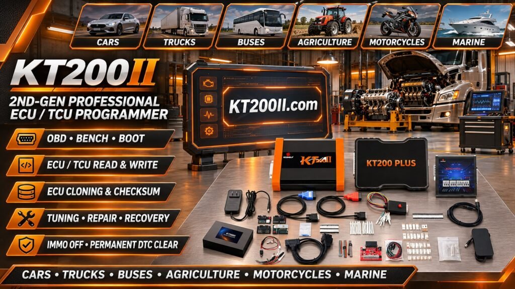
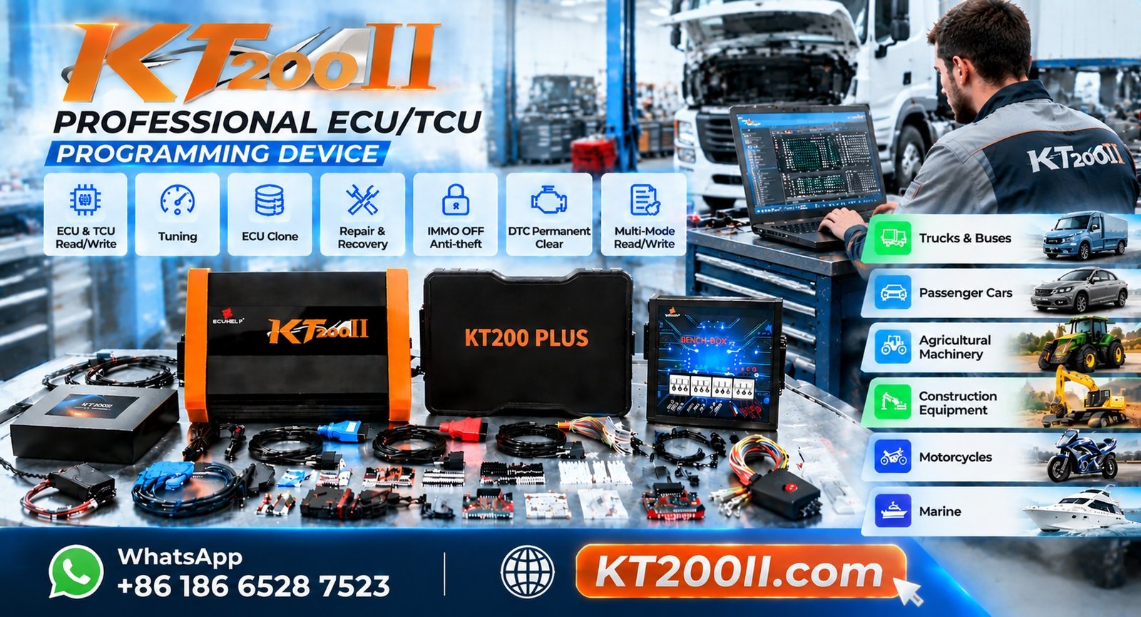
KT200II is an ECU and TCU programming solution designed for compatible automotive controller applications.
Depending on the ECU, software version and supported programming protocol, available functions may include:
- ECU and TCU identification.
- Supported OBD programming operations.
- Supported Bench programming operations.
- Selected Flash Read operations.
- Selected Flash Write operations.
- Selected EEPROM operations.
- Supported specialized programming procedures.
When using KT200II, technicians should confirm the exact ECU model and programming method before making electrical connections.
For Bench applications, always follow the corresponding wiring diagram. Correct CAN-H, CAN-L, power and ground connections are essential when required by the ECU.
Remember that communication capability and memory programming capability are two different things. Successful ECU identification does not automatically guarantee that all memory operations are supported.
Useful resources:
- KT200II Official Website
- KT200II Product Information
- KT200II Operation Modes
- KT200II Software
- KT200II Supported ECU List
- KT200II Technical Blog
For purchasing information, visit the ECUHELP Official Store.
14. Common Mistakes When Working with CAN and K-Line
Communication problems are sometimes caused by basic connection mistakes rather than software or ECU failures.
Common mistakes include:
- Confusing CAN-H with CAN-L.
- Using an incorrect ECU pinout.
- Assuming every ECU uses CAN communication.
- Ignoring K-Line on older vehicle applications.
- Measuring resistance while the circuit is powered.
- Ignoring required ECU power and ground connections.
- Selecting an incorrect programming protocol.
- Assuming successful identification means complete programming support.
Accurate wiring documentation and correct protocol selection are essential for professional ECU programming.
15. Best Practices for Automotive ECU Communication
Before starting a programming or diagnostic operation, technicians should follow a consistent inspection procedure.
- Identify the exact ECU manufacturer and model.
- Check the correct wiring diagram.
- Identify the required communication protocol.
- Verify CAN-H and CAN-L where applicable.
- Check K-Line connections where applicable.
- Verify ECU power and ground.
- Inspect cables and connectors.
- Check network conditions using appropriate test equipment.
- Select the correct programming protocol.
- Confirm supported memory operations.
- Maintain stable electrical conditions.
- Save original ECU data where supported.
Frequently Asked Questions
What is the main difference between CAN Bus and K-Line?
CAN Bus generally uses two differential communication wires, CAN-H and CAN-L, while K-Line normally uses one primary communication signal wire. Both are used in automotive electronic communication.
Are CAN-H and CAN-L interchangeable?
No. CAN-H and CAN-L have different signal roles and must be connected to their correct terminals.
Can a vehicle use both CAN Bus and K-Line?
Yes. Some vehicles contain multiple communication systems, and different electronic modules may use different protocols.
How do I check CAN Bus resistance?
For a conventional high-speed CAN network, approximately 60 ohms between CAN-H and CAN-L is commonly expected when the network is powered off and both 120-ohm termination resistors are present. Actual results depend on network architecture.
Why does my ECU not communicate even when CAN wiring is correct?
Possible causes include missing power, poor ground, incorrect protocol selection, wake-up requirements, gateway issues, damaged communication circuits or an ECU hardware fault.
Is CAN FD the same as standard CAN?
No. CAN FD extends conventional CAN with larger data payloads and support for a faster data phase.
Does Bench programming always use CAN?
No. Depending on the ECU, Bench communication may use CAN or another supported communication interface.
Can KT200II program all CAN and K-Line ECUs?
No. Compatibility depends on the exact ECU, supported protocol, software version and available programming operations. Check the official support information before starting.
Conclusion
CAN Bus and K-Line are important communication technologies in automotive electronics. Understanding their electrical characteristics and applications helps technicians identify connection problems and prepare for ECU programming operations.
CAN Bus is widely used in modern vehicle networks, while K-Line remains relevant for many older diagnostic applications.
For professional ECU programming, correct protocol identification, accurate wiring, stable power and verified controller compatibility are all essential.
To learn more about ECU programming equipment and supported controller applications, visit the KT200II Official Website and explore the ECUHELP Official Store.