Automotive ECU Communication Protocols Explained: CAN, CAN FD, K-Line, UDS and DoIP
Automotive ECU Communication Protocols Explained: CAN, CAN FD, K-Line, UDS and DoIP
Modern vehicles contain dozens of electronic control units responsible for managing engine performance, automatic transmissions, braking systems, airbags, body electronics and other vehicle functions.
These electronic modules must exchange information with each other and communicate with diagnostic scanners and ECU programming equipment. To make this possible, automotive manufacturers use different communication protocols and network technologies.
Understanding ECU communication protocols is essential for automotive technicians who perform vehicle diagnostics, ECU programming, memory operations and electronic control module repairs.
Different protocols have different electrical characteristics, communication speeds, message structures and diagnostic capabilities. Selecting an incorrect communication method can result in failed identification, unstable communication or unsuccessful programming operations.
In this KT200II technical guide, we explain the most important automotive communication technologies, including CAN, CAN FD, K-Line, LIN, UDS, KWP2000, ISO-TP and DoIP.
1. What Are Automotive ECU Communication Protocols?
An automotive communication protocol is a set of rules that determines how electronic control units exchange information.
These rules define how data is transmitted, received, interpreted and verified between connected electronic devices.
Depending on the vehicle architecture, communication may take place between:
- Engine Control Module (ECM).
- Transmission Control Module (TCM).
- Anti-lock Braking System (ABS).
- Electronic Stability Control (ESC).
- Body Control Module (BCM).
- Airbag Control Module (SRS).
- Instrument Cluster.
- Gateway Control Module.
- Diagnostic scanners and programming equipment.
For example, the engine ECU may send engine speed and torque information to the transmission controller. The TCU uses this information to manage gear changes and transmission operation.
Communication protocols make this exchange possible.
2. Understanding the Difference Between a Physical Layer and a Diagnostic Protocol
One important concept in automotive electronics is the difference between a communication network and a diagnostic protocol.
They are related, but they do not describe exactly the same thing.
Physical and Data Link Layers
These define how electrical signals are transmitted and how messages are organized on the communication network.
Examples include:
- CAN.
- CAN FD.
- LIN.
- Automotive Ethernet.
- K-Line electrical communication.
Diagnostic Protocols
Diagnostic protocols define how diagnostic requests and responses are structured and interpreted.
Examples include:
- UDS.
- KWP2000.
- OBD-II diagnostic services.
- Manufacturer-specific diagnostic services.
For example, UDS can operate over CAN using ISO-TP for message transport, or over Ethernet using DoIP.
Therefore, identifying CAN communication does not automatically identify the diagnostic protocol used by the ECU.
3. What Is CAN Bus Communication?
CAN stands for Controller Area Network. It is one of the most widely used communication technologies in automotive electronic systems.
CAN allows multiple electronic control units to exchange information through a shared communication bus.
Instead of requiring a separate communication wire between every pair of modules, CAN allows multiple controllers to communicate through a common network.
A conventional high-speed CAN connection uses two signal wires:
- CAN-H: CAN High.
- CAN-L: CAN Low.
CAN uses differential signaling, meaning that communication is based on the voltage difference between these two wires.
How Does CAN Communication Work?
CAN uses message-based communication rather than assigning a dedicated communication channel to each ECU.
Each CAN message contains an identifier that determines its priority and meaning within the network.
When multiple controllers attempt to transmit simultaneously, CAN arbitration allows the highest-priority message to continue without corrupting the communication.
This makes CAN suitable for real-time communication between vehicle control systems.
Common CAN Applications
- Engine management.
- Automatic transmission control.
- ABS and stability control.
- Body electronics.
- Steering systems.
- Vehicle diagnostic communication.
4. What Is CAN FD?
CAN FD stands for Controller Area Network Flexible Data-Rate.
It is an extension of conventional CAN designed to support larger data payloads and higher data transmission speeds during the data phase.
Traditional Classical CAN supports a maximum data payload of 8 bytes per frame.
CAN FD supports payloads of up to 64 bytes per frame.
This allows more information to be transferred with fewer frames in suitable applications.
Advantages of CAN FD
- Larger data payloads.
- Higher potential data transmission speed.
- More efficient communication for larger data transfers.
- Support for modern vehicle electronic architectures.
- Improved communication efficiency in suitable networks.
CAN FD can use a faster data phase while retaining a compatible arbitration phase, depending on the network configuration.
However, the actual communication speed depends on the controller, transceiver, wiring and network design.
Classical CAN equipment does not automatically support CAN FD. Compatibility must be verified before attempting communication with a CAN FD-based ECU.
5. What Is LIN Bus?
LIN stands for Local Interconnect Network.
It is a relatively low-cost automotive communication network commonly used for less demanding electronic applications.
Unlike conventional high-speed CAN, LIN uses a single-wire communication bus and a master-slave communication architecture.
Typical LIN applications include:
- Electric window controls.
- Mirror adjustment systems.
- Seat adjustment modules.
- Sunroof control.
- Interior lighting.
- Selected climate control components.
LIN is generally used for communication between a central controller and simpler electronic devices.
It is often used alongside CAN in vehicle network architectures rather than replacing CAN completely.
6. What Is K-Line Communication?
K-Line is an older automotive diagnostic communication technology used in many vehicles before CAN became widespread.
It uses a single communication wire and is commonly associated with ISO 9141 and ISO 14230 diagnostic standards.
Depending on the implementation, K-Line communication may use different initialization and message timing procedures.
Common K-Line Applications
- Older engine control units.
- Legacy transmission controllers.
- Older European vehicle diagnostic systems.
- Selected body control modules.
- Older OBD diagnostic applications.
Some K-Line applications use initialization procedures before diagnostic communication begins.
Because K-Line is an older technology, communication speeds and capabilities are generally more limited than modern CAN-based systems.
7. What Is KWP2000?
KWP2000 stands for Keyword Protocol 2000.
It is an automotive diagnostic communication protocol standardized under ISO 14230.
KWP2000 was widely used in different vehicle electronic systems, particularly in older diagnostic architectures.
Depending on the implementation, KWP2000 can operate over K-Line or other supported transport arrangements.
Common diagnostic functions may include:
- ECU identification.
- Reading diagnostic trouble codes.
- Clearing diagnostic trouble codes.
- Reading selected data parameters.
- Executing supported diagnostic routines.
- Accessing programming-related services.
Not every KWP2000 implementation supports all these functions.
Different manufacturers may also implement additional proprietary diagnostic features.
8. What Is UDS?
UDS stands for Unified Diagnostic Services.
It is a modern automotive diagnostic protocol standardized under ISO 14229.
UDS provides a structured set of diagnostic services that allow diagnostic equipment to communicate with electronic control units.
Compared with older diagnostic protocols, UDS supports a broader range of diagnostic and programming-related operations.
Common UDS Services
- Diagnostic Session Control.
- ECU Reset.
- Security Access.
- Read Data By Identifier.
- Write Data By Identifier.
- Read DTC Information.
- Clear Diagnostic Information.
- Routine Control.
- Request Download.
- Request Upload.
- Transfer Data.
- Request Transfer Exit.
These services are identified by service identifiers, commonly called SIDs.
Why Is UDS Important for ECU Programming?
Many modern ECU programming applications use UDS-based services to manage diagnostic sessions and supported memory operations.
For example, a programming procedure may require the diagnostic equipment to enter a programming session, perform the required security authorization and then transfer data using supported services.
However, UDS support alone does not guarantee that an ECU can be programmed.
The exact ECU application, security requirements, programming sequence and supported memory operations must also be available.
9. What Is ISO-TP?
ISO-TP is a transport protocol defined under ISO 15765-2.
It is commonly used to transport diagnostic messages over CAN networks.
Classical CAN frames can carry only a limited amount of data. Some diagnostic messages, especially programming-related data transfers, are larger than a single CAN frame.
ISO-TP allows larger diagnostic messages to be divided into smaller frames and reassembled by the receiving device.
Important ISO-TP Frame Types
- Single Frame: Transmits a message that fits into one frame.
- First Frame: Announces the beginning of a multi-frame message.
- Consecutive Frame: Carries subsequent portions of the message.
- Flow Control Frame: Manages the transmission of multi-frame data.
ISO-TP is particularly important in ECU diagnostics and programming because it enables the transfer of larger data blocks through CAN communication.
10. What Is DoIP?
DoIP stands for Diagnostics over Internet Protocol.
It is an automotive diagnostic communication technology standardized under ISO 13400.
DoIP uses Ethernet-based communication to exchange diagnostic information between testing equipment and vehicle electronic control units.
As vehicle electronic architectures become more complex, Ethernet-based diagnostics provide higher communication bandwidth than traditional CAN networks.
Advantages of DoIP
- High-speed diagnostic communication.
- Support for larger data transfers.
- Efficient ECU programming workflows.
- Integration with modern vehicle network architectures.
- Support for UDS diagnostic communication over Ethernet.
DoIP is increasingly relevant in modern vehicles, particularly those with advanced electronic architectures and high-speed diagnostic requirements.
However, DoIP compatibility requires suitable vehicle interfaces, network configuration and diagnostic software support.
11. Comparison of Major Automotive Communication Technologies
| Technology | Main Purpose | Typical Application |
|---|---|---|
| CAN | Vehicle network communication | Engine, transmission, ABS |
| CAN FD | Higher-capacity CAN communication | Modern vehicle networks |
| LIN | Low-cost local communication | Windows, mirrors, seats |
| K-Line | Legacy diagnostic communication | Older ECUs |
| KWP2000 | Diagnostic services | Legacy vehicle diagnostics |
| UDS | Advanced diagnostic services | Modern ECU diagnostics |
| ISO-TP | Transport of diagnostic messages | UDS over CAN |
| DoIP | Diagnostics over Ethernet | Modern vehicle platforms |
These technologies operate at different layers of the communication architecture. Some can work together rather than serving as direct alternatives.
12. What Is the Difference Between OBD-II and UDS?
OBD-II and UDS are often discussed together, but they serve different purposes.
OBD-II defines standardized diagnostic requirements and services, particularly for emissions-related monitoring and fault information.
UDS is a broader diagnostic protocol that supports additional diagnostic, control and programming-related services.
| Feature | OBD-II | UDS |
|---|---|---|
| Main purpose | Standardized vehicle diagnostics | Enhanced ECU diagnostics |
| Fault information | Standardized emissions DTCs | Broader diagnostic information |
| Data access | Standardized parameters | Manufacturer-defined identifiers |
| Programming services | Limited generic scope | Supports programming-related services |
| Implementation | Vehicle compliance dependent | ECU and manufacturer dependent |
A diagnostic tool may support generic OBD-II communication without supporting the enhanced UDS functions required by a particular ECU.
13. Common OBD-II Communication Pins
The standard 16-pin OBD-II connector provides different terminals for vehicle diagnostic communication and electrical supply.
Some commonly used connections include:
- Pin 4: Chassis Ground.
- Pin 5: Signal Ground.
- Pin 6: CAN High.
- Pin 7: K-Line.
- Pin 14: CAN Low.
- Pin 16: Battery Positive.
These are common standardized assignments, but not every vehicle uses every pin for the same purpose.
Additional manufacturer-specific connections and diagnostic arrangements may also exist.
Always verify the vehicle wiring diagram before making electrical connections. Never assume that an ECU connector uses the same pin assignments as the OBD-II diagnostic socket.
14. Why Do Different ECUs Use Different Communication Protocols?
Vehicle manufacturers select communication technologies according to system requirements, production costs, processing demands and vehicle architecture.
For example:
- Engine ECUs may use CAN or CAN FD for vehicle network communication.
- Transmission controllers may use CAN-based diagnostic communication.
- Older controllers may use K-Line and KWP2000.
- Body electronics may use LIN for smaller local networks.
- Modern vehicle platforms may use Ethernet and DoIP.
Different systems also have different requirements for communication speed, message priority, reliability and diagnostic access.
15. Why Does an ECU Fail to Communicate?
Communication failures are common during vehicle diagnostics and ECU programming.
However, a failed communication attempt does not automatically mean that the ECU is defective.
Possible causes include:
- Incorrect communication protocol selection.
- Incorrect CAN-H and CAN-L connections.
- Missing ECU power supply.
- Poor ground connection.
- Missing ignition or wake-up signal.
- Damaged communication wiring.
- Defective CAN transceiver.
- Incorrect baud rate or communication configuration.
- Unsupported diagnostic services.
- Gateway restrictions.
- Security access requirements.
- Internal ECU hardware failure.
Technicians should investigate the complete communication path before replacing an ECU.
16. How to Diagnose CAN Communication Problems
CAN-related communication problems require systematic electrical and network diagnosis.
Step 1: Verify Power and Ground
Check that the target ECU receives the required power supply and has reliable ground connections.
Step 2: Verify CAN Wiring
Confirm that CAN-H and CAN-L are connected to the correct terminals.
Step 3: Inspect the Wiring Harness
Look for damaged insulation, corrosion, loose terminals and short circuits.
Step 4: Check Network Conditions
Where appropriate, use an oscilloscope to inspect CAN signals and identify abnormal communication behavior.
Step 5: Check Network Termination
For a conventional high-speed CAN network, the correct termination arrangement is important. Resistance measurements should be performed only under appropriate power-off conditions and according to the network design.
Step 6: Verify the Communication Protocol
Confirm that the diagnostic equipment supports the communication method and configuration required by the target ECU.
Step 7: Check Gateway and Security Conditions
Some vehicles require gateway authorization or additional security access before enhanced diagnostic operations can be performed.
17. How Communication Protocols Affect ECU Programming
ECU programming requires more than establishing basic communication.
The programming equipment must support the complete communication procedure required by the target controller.
Depending on the ECU, this may involve:
- Initial communication establishment.
- ECU identification.
- Diagnostic session selection.
- Security authorization.
- Memory access preparation.
- Data transfer.
- Programming verification.
- Session termination.
Different ECUs may use different combinations of diagnostic services, transport protocols and programming sequences.
Therefore, a programmer supporting CAN communication does not automatically support every CAN-based ECU.
Likewise, support for UDS does not guarantee support for every UDS-based programming application.
18. What Should Technicians Check Before Selecting ECU Programming Equipment?
Before purchasing or using an ECU programmer, technicians should evaluate several compatibility factors.
- ECU manufacturer.
- Exact ECU part number.
- Hardware version.
- Software version.
- Microcontroller family.
- Communication protocol.
- Required programming mode.
- Supported Flash operations.
- Supported EEPROM operations.
- Required adapters and wiring harnesses.
- Security and gateway requirements.
These details help determine whether the equipment can perform the required operation on the specific controller.
19. How KT200II Fits into Professional ECU Programming
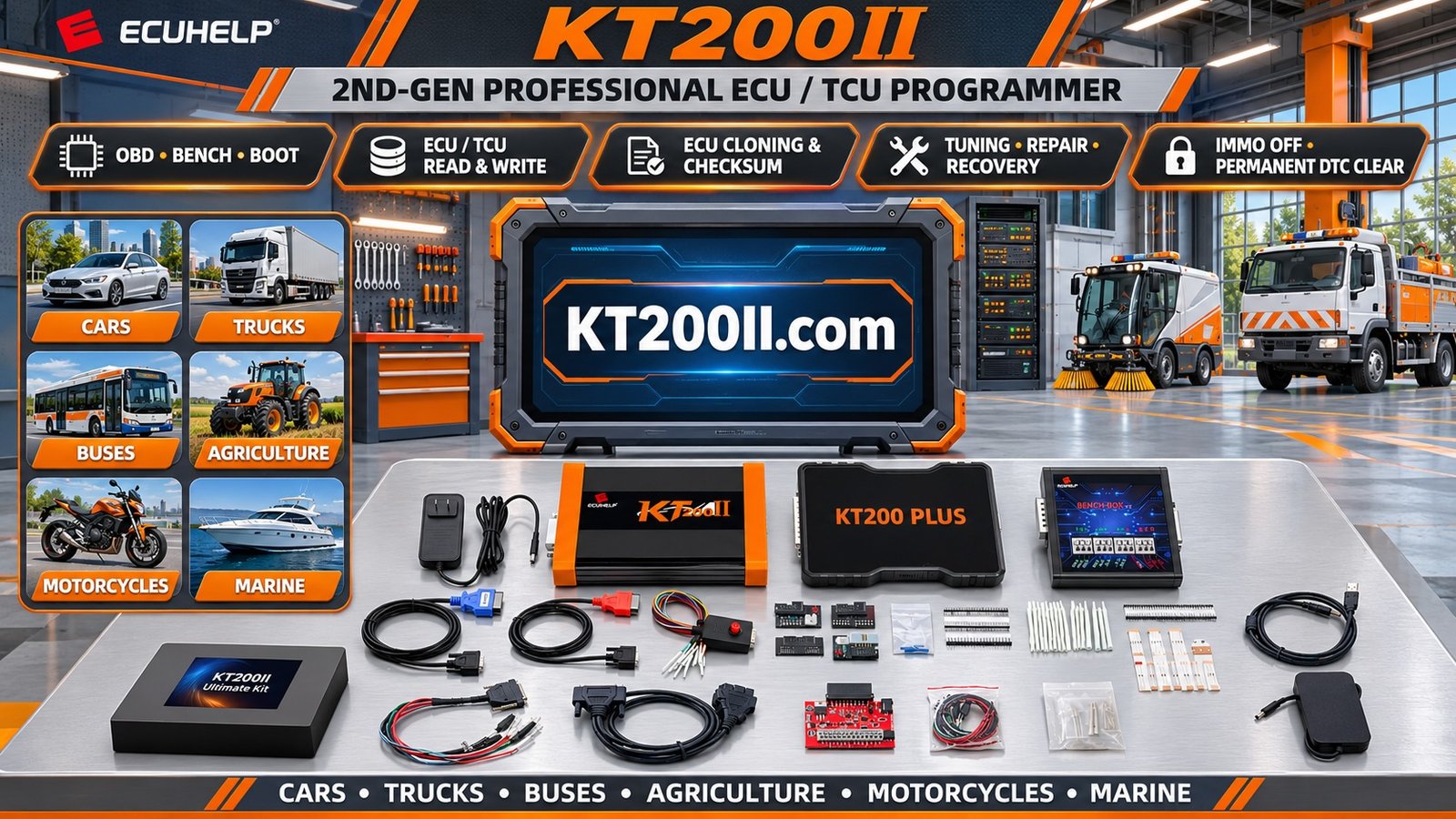
KT200II is a professional ECU and TCU programming tool designed for supported automotive electronic control units.
Depending on the released software protocols and exact ECU application, KT200II supports different programming procedures and connection methods.
When evaluating compatibility, technicians should check:
- Exact ECU or TCU identification.
- Supported vehicle application.
- Available programming mode.
- Required communication connections.
- Supported memory operations.
- Additional adapter requirements.
It is important to understand that a programming tool supporting one CAN-based ECU does not automatically support every controller using CAN communication.
Compatibility depends on the complete ECU application and its supported programming protocol.
Explore the KT200II ECU Programmer for product information.
Visit the KT200II Operation Modes page to learn about supported connection methods.
Check the KT200II Support List before selecting an ECU or TCU programming operation.
For software information and updates, visit the KT200II Software page.
20. Common Mistakes When Working with ECU Communication Protocols
Some communication problems are caused by incorrect assumptions rather than defective hardware.
Common mistakes include:
- Confusing CAN communication with UDS diagnostics.
- Assuming CAN and CAN FD are interchangeable.
- Using an incorrect ECU pinout.
- Reversing CAN-H and CAN-L connections.
- Ignoring power supply requirements.
- Assuming every ECU supports OBD programming.
- Confusing Bench and Boot programming procedures.
- Assuming that generic OBD-II access provides complete ECU access.
- Ignoring gateway authorization requirements.
- Assuming all ECUs from the same manufacturer use identical protocols.
Accurate identification and correct technical documentation are essential for reliable automotive communication and programming.
21. Automotive ECU Communication Diagnostic Checklist
Use this checklist when investigating an ECU communication problem:
- Vehicle manufacturer and model identified.
- Target ECU identified.
- ECU hardware part number recorded.
- Communication protocol identified where possible.
- Required programming mode confirmed.
- Correct connection diagram obtained.
- Power supply checked.
- Ground connections verified.
- CAN-H and CAN-L checked where applicable.
- K-Line connection checked where applicable.
- Communication wiring inspected.
- Network conditions evaluated.
- Diagnostic software compatibility confirmed.
- Gateway requirements considered.
- Security access requirements checked.
- Programming application compatibility verified.
Frequently Asked Questions
What is the most common automotive ECU communication protocol?
CAN is one of the most widely used automotive communication technologies. However, vehicles may also use CAN FD, LIN, K-Line and Automotive Ethernet depending on the system and generation.
What is the difference between CAN and CAN FD?
CAN FD supports larger data payloads of up to 64 bytes per frame and can use a faster data phase. Classical CAN supports up to 8 bytes per frame.
Is UDS the same as CAN?
No. CAN is a communication network technology, while UDS is a diagnostic protocol. UDS can operate over CAN using ISO-TP or over Ethernet using DoIP.
What is KWP2000 used for?
KWP2000 is an automotive diagnostic protocol used in many older vehicle electronic systems. It is commonly associated with K-Line communication.
What is the difference between K-Line and CAN?
K-Line generally uses a single communication wire and is common in older diagnostic systems. CAN uses two differential signal wires and supports multi-controller network communication.
What is ISO-TP used for?
ISO-TP allows diagnostic messages larger than a single CAN frame to be divided into multiple frames and transmitted over CAN.
What is DoIP?
DoIP is a diagnostic communication technology that uses automotive Ethernet and Internet Protocol-based communication. It is standardized under ISO 13400.
Can an ECU programmer support CAN but not UDS?
Yes. Supporting the CAN communication interface does not automatically mean that a device supports UDS diagnostic services or the programming sequence required by a particular ECU.
Why can a diagnostic scanner identify an ECU but fail to program it?
Identification and programming require different levels of access. Programming may require additional diagnostic sessions, security authorization, supported memory services and specific application protocols.
Does every vehicle use the same CAN communication speed?
No. Communication speeds vary depending on the network design, vehicle manufacturer and electronic system.
Can CAN-H and CAN-L be connected incorrectly?
Yes. Reversed or incorrectly connected communication wires can prevent normal communication and may cause other electrical problems. Always verify the exact wiring diagram.
Does KT200II support every CAN or UDS-based ECU?
No. KT200II supports specific ECU and TCU applications. Compatibility must be confirmed using the exact hardware and the official supported application list.
Conclusion
Automotive ECU communication protocols are fundamental to modern vehicle diagnostics, electronic control and programming operations.
Understanding the differences between CAN, CAN FD, LIN, K-Line, UDS, KWP2000, ISO-TP and DoIP helps technicians identify the correct communication method for different vehicle electronic systems.
It is particularly important to distinguish communication hardware from diagnostic protocols. Supporting a particular network technology does not automatically guarantee access to every diagnostic service or programming function.
Before attempting ECU programming, technicians should identify the exact controller, verify the communication architecture, check the wiring and confirm that the selected programming equipment supports the required application.
KT200II provides ECU and TCU programming capabilities for supported applications. Visit the KT200II Product Page, review the Supported ECU List and explore the KT200II Technical Blog for more professional automotive programming information.
Correct communication protocol identification is an essential step toward reliable ECU diagnostics and successful programming operations.