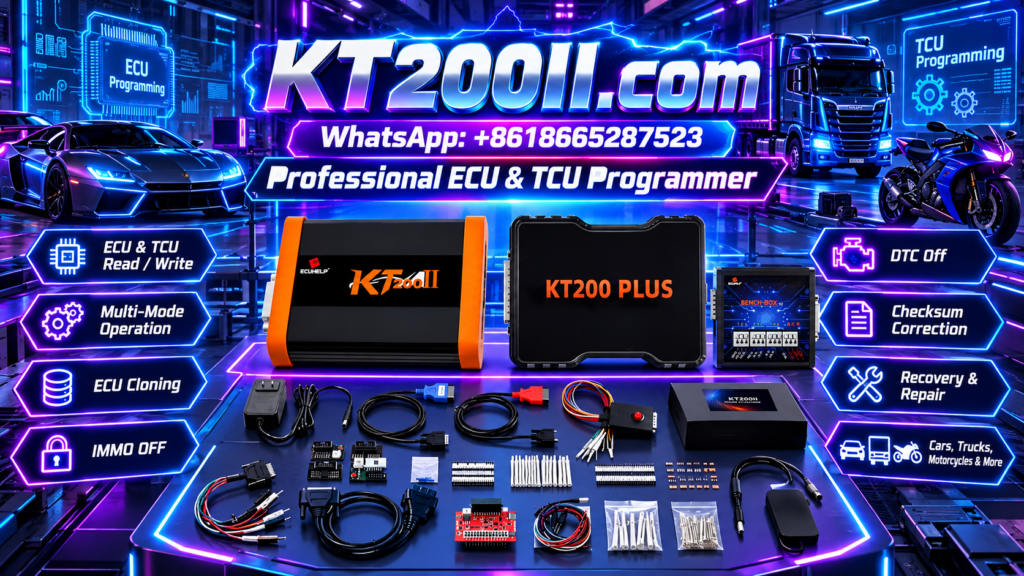
KT200II ECU Programming Adapter Selection Guide
KT200II OFFICIAL TECHNICAL GUIDE
KT200II ECU Programming Adapter Selection Guide
The correct cable and adapter are essential for establishing a stable connection before reading, writing, cloning or verifying a supported ECU with the KT200II ECU Programmer.
Why Adapter Selection Matters
Different ECUs and TCUs may require different connectors, pin layouts and communication interfaces. A cable that physically fits an adapter does not automatically mean that the wiring or protocol is correct for the control unit.
Before selecting an adapter, search the exact ECU or TCU in the official KT200II supported list. Confirm the vehicle, module type, microcontroller, read/write function and connection method shown in the record.
Adapter Selection Checklist
| Check | What to Confirm | Why It Matters |
|---|---|---|
| ECU record | Exact ECU or TCU entry in the support database | Prevents selecting an adapter for a similar module. |
| Operation mode | OBD, Bench, Boot, JTAG or BDM | Each mode may require a different connection setup. |
| Connector type | ECU plug, bench adapter and cable interface | Ensures the connection is mechanically secure. |
| Wiring reference | Approved pinout and terminal arrangement | Prevents power and communication wiring errors. |
| Cable condition | Pins, insulation, locks and strain relief | Reduces intermittent communication problems. |
Step 1: Confirm the ECU and Mode
Start with the control unit, not the adapter drawer. Identify the ECU part number, hardware number, software information and vehicle application. Then open the KT200II support database and confirm the listed operation mode.
The KT200II operation modes guide explains the difference between OBD, Bench, Boot, JTAG and BDM. Select the adapter only after the supported mode is known.
Step 2: Inspect the Adapter and Cable
- Check that connector pins are straight, clean and firmly mounted.
- Inspect the cable insulation for cuts, crushing or exposed conductors.
- Confirm that locking tabs close completely.
- Check that labels on the adapter match the intended connection.
- Keep different adapters physically separated and clearly labeled.
- Do not force a connector that does not align naturally.
A damaged or loose adapter can create an intermittent fault that appears to be a software or ECU problem.
Bench Adapter Preparation
For Bench operations, place the ECU on a stable non-conductive surface and use the adapter listed for the exact module. Confirm the power, ground and communication connections before applying power.
- Match the adapter label with the verified ECU record.
- Connect the ECU-side plug without applying sideways force.
- Check power and ground connections against the approved pinout.
- Attach the KT200II interface and USB cable securely.
- Apply power only after the complete wiring has been inspected.
OBD Cable Preparation
When OBD mode is supported, use the approved vehicle-side cable and diagnostic connector. Inspect the vehicle socket for bent terminals, moisture or aftermarket damage before connecting the KT200II interface.
- Confirm that the vehicle and ECU record supports OBD access.
- Connect the cable straight into the diagnostic socket.
- Prevent the cable from hanging under tension during the operation.
- Use stable vehicle power support when required by the procedure.
- Follow the ignition instructions shown by KT200II software.
Stop Conditions Before Communication
- The adapter does not match the support record.
- The connector requires force or does not lock correctly.
- Power, ground or communication pins are not confirmed.
- A cable becomes hot or shows visible damage.
- The software identifies a different ECU family.
- The module is not listed for the selected operation mode.
Communication Check Before Writing
After connecting the adapter, install the approved package from the official KT200II software download page. Select the exact protocol and read identification data first.
- Confirm that the KT200II interface is detected.
- Read ECU identification where supported.
- Compare the detected data with the physical module.
- Save the original data before writing.
- Stop if the identification or communication status is unexpected.
Official KT200II Resources
Get the Official KT200II ECU Programmer
The official KT200II ECU Programmer is available from the ECUHELP global store at HELPECU.com.
For help selecting an adapter, checking a cable or confirming ECU compatibility, contact the official team on WhatsApp: +86 18665287523.