TCU Programming Guide: Transmission Control Module Reading, Writing and Diagnostics
TCU Programming Guide: Transmission Control Module Reading, Writing and Diagnostics
The Transmission Control Unit (TCU) is an important electronic component in modern automatic transmission systems. It manages gear selection, clutch operation, hydraulic pressure, shift timing and communication with other vehicle control modules.
As automatic transmissions become increasingly electronic, professional automotive technicians need to understand TCU architecture, memory organization, communication protocols and programming procedures.
TCU programming equipment can support different operations depending on the transmission controller, hardware architecture and available communication protocols.
This guide explains how transmission control modules work, how TCU reading and writing are performed, and the differences between OBD, Bench and Boot programming.
1. What Is a Transmission Control Unit?
A Transmission Control Unit is an electronic controller responsible for managing automatic transmission operation.
Depending on the transmission design, the TCU may control:
- Gear selection.
- Gear shifting strategies.
- Clutch engagement.
- Hydraulic pressure regulation.
- Torque converter lockup.
- Transmission temperature monitoring.
- Shift adaptation.
- Communication with the engine ECU.
Some vehicles use a separate TCU, while others integrate transmission control functions into a combined engine and transmission controller or mechatronic assembly.
2. Understanding TCU Architecture
Modern transmission controllers combine electronic hardware, embedded software and communication interfaces.
Depending on the transmission platform, a TCU may contain:
- Automotive microcontroller.
- Flash memory.
- EEPROM or Data Flash.
- RAM.
- Power management circuits.
- CAN communication interfaces.
- Sensor input circuits.
- Solenoid driver circuits.
- Temperature monitoring circuits.
The exact hardware architecture varies between manufacturers and transmission families.
3. How Does a TCU Control Automatic Shifting?
The TCU continuously processes information from vehicle sensors and other control modules to determine the appropriate transmission operating strategy.
Important input signals may include:
- Vehicle speed.
- Engine speed.
- Transmission input shaft speed.
- Transmission output shaft speed.
- Throttle position.
- Accelerator pedal position.
- Transmission oil temperature.
- Brake pedal status.
Based on these signals, the TCU calculates when to shift gears and how to control clutch and hydraulic pressure.
4. Understanding Transmission Solenoid Control
Automatic transmissions use electronic solenoids to control hydraulic circuits and clutch operation.
Depending on the transmission design, the TCU may control:
- Shift solenoids.
- Pressure control solenoids.
- Clutch control solenoids.
- Torque converter lockup solenoids.
Incorrect solenoid operation can cause harsh shifting, delayed engagement, slipping or transmission warning messages.
5. Understanding TCU Flash Memory
Flash memory stores software and calibration information used by the transmission controller.
Depending on the TCU architecture, Flash memory may contain:
- Transmission application software.
- Gear shifting strategies.
- Clutch control parameters.
- Hydraulic pressure control maps.
- Torque management information.
- Diagnostic functions.
Supported Flash reading operations allow technicians to retrieve selected memory data for backup and compatible programming applications.
6. Understanding EEPROM and Data Flash
Non-volatile memory stores selected information even when the vehicle battery is disconnected.
Depending on the transmission controller, persistent memory may contain:
- Transmission configuration.
- Adaptation information.
- Identification data.
- Selected operating parameters.
- Manufacturer-specific information.
Some TCUs use separate EEPROM devices, while others use internal Data Flash or other memory technologies.
Technicians should identify the actual memory architecture before performing backup or transfer operations.
7. What Is TCU Reading?
TCU reading is the process of retrieving supported electronic data from a transmission control module.
Depending on the controller and programming protocol, reading operations may include:
- TCU identification.
- Software identification.
- Flash memory reading.
- EEPROM reading where supported.
- Original data backup.
- Selected configuration data retrieval.
Reading the original data before programming can help technicians preserve supported information for recovery or compatible replacement procedures.
8. What Is TCU Writing?
TCU writing transfers compatible software or memory data into a transmission controller.
Depending on the supported hardware and protocol, operations may include:
- Flash writing.
- Supported EEPROM writing.
- Software restoration.
- Compatible calibration updates.
- Selected memory transfer operations.
Writing must use data compatible with the exact controller hardware and software configuration.
Incorrect files or interrupted programming operations may cause communication problems or controller malfunction.
9. OBD Programming for TCU Modules
OBD programming communicates with supported transmission controllers through the vehicle diagnostic connector.
Depending on the vehicle and programming protocol, available operations may include:
- TCU identification.
- Supported memory reading.
- Supported memory writing.
- Software identification.
- Selected diagnostic operations.
The main advantage is that the transmission controller generally remains installed in the vehicle.
However, not every TCU supports complete memory access through OBD.
10. Bench Programming for Transmission Controllers
Bench programming connects directly to a removed transmission controller using supported external electrical connections.
Depending on the TCU hardware, connections may include:
- Battery power.
- Ignition-switched power.
- Ground.
- CAN-H.
- CAN-L.
- Additional activation signals.
Bench programming may support TCU identification, memory reading, memory writing and selected programming operations.
Always verify the exact connector pinout before connecting a programming tool.
11. Understanding Boot Programming
Boot programming provides supported low-level access to selected transmission controller microcontrollers.
Depending on the processor and programming protocol, supported operations may include:
- Processor identification.
- Flash reading.
- Flash writing.
- Selected memory operations.
- Specific recovery procedures.
Boot access requirements vary between transmission controller architectures.
Not every TCU supports Boot programming.
12. Common Automatic Transmission Families
Modern vehicles use different automatic transmission designs, each with its own control module architecture and programming requirements.
Examples of widely used transmission families include:
- Zf 6HP automatic transmissions.
- Zf 8HP automatic transmissions.
- Mercedes-Benz 7G-Tronic transmissions.
- Mercedes-Benz 9G-Tronic transmissions.
- Volkswagen DSG transmissions.
- Getrag dual-clutch transmissions.
- Aisin automatic transmissions.
- Ford automatic transmission systems.
- GM automatic transmission systems.
These transmission families contain different generations and controller configurations.
Knowing the transmission family alone is not sufficient to determine programming compatibility.
13. Understanding Mechatronic Transmission Controllers
Some modern automatic transmissions use an integrated mechatronic assembly.
This assembly combines electronic control components and hydraulic transmission functions.
Depending on the design, it may include:
- Transmission control electronics.
- Hydraulic control circuits.
- Solenoid valves.
- Pressure sensors.
- Temperature sensors.
- Internal wiring and connectors.
When working with mechatronic units, technicians should identify the exact hardware version and understand whether the controller is serviceable separately or integrated into the transmission assembly.
14. Understanding TCU Cloning
TCU cloning involves transferring supported electronic memory data from an original controller to compatible replacement hardware.
Depending on the transmission controller, this may involve:
- Original Flash backup.
- Supported EEPROM backup.
- Replacement hardware verification.
- Compatible memory transfer.
- Configuration checks.
- Final diagnostic verification.
Not every transmission controller supports conventional cloning.
Hardware compatibility, software versions, memory structure and manufacturer-specific security requirements must be verified before transferring data.
15. Understanding TCU Adaptation and Calibration
Automatic transmissions may use adaptation values to compensate for clutch wear, hydraulic characteristics and operating conditions.
Depending on the transmission design, adaptation information may relate to:
- Clutch engagement.
- Hydraulic pressure compensation.
- Shift timing.
- Torque converter operation.
- Transmission temperature.
Replacing a TCU or transmission mechatronic unit may require manufacturer-specified coding, initialization or adaptation procedures.
Memory transfer alone does not automatically complete every required replacement procedure.
16. Common TCU Problems
Transmission problems can originate from electronic, hydraulic, mechanical or software-related faults.
Common symptoms include:
- Harsh gear shifting.
- Delayed gear engagement.
- Transmission slipping.
- Gear selection problems.
- Transmission warning lights.
- Communication failure.
- Emergency operating mode.
- Abnormal transmission temperature readings.
These symptoms do not automatically indicate TCU failure.
Technicians should inspect transmission fluid, wiring, connectors, sensors, solenoids and hydraulic components before replacing the controller.
17. How to Troubleshoot TCU Communication Problems
A systematic diagnostic procedure helps identify the source of transmission controller communication failures.
Step 1: Identify the Transmission
Record the vehicle model, transmission family and complete TCU hardware number.
Step 2: Check Power Supply
Verify the battery voltage and required TCU power connections.
Step 3: Inspect Ground Connections
Check ground connections, connector condition and electrical continuity.
Step 4: Check Communication Wiring
Inspect CAN-H, CAN-L and other applicable communication circuits.
Step 5: Confirm Protocol Compatibility
Verify that the selected programming protocol supports the exact transmission controller.
Step 6: Inspect the Controller
If external connections are correct, further electronic inspection may be necessary.
18. Best Practices for TCU Programming
Professional technicians should follow these practices when working with transmission control modules.
- Record the complete TCU hardware number.
- Identify the exact transmission family.
- Confirm processor and memory architecture where necessary.
- Verify programming protocol compatibility.
- Use the correct wiring diagram.
- Maintain stable electrical power.
- Back up supported original memory.
- Verify replacement hardware compatibility.
- Check software and calibration compatibility.
- Avoid interrupting Flash writing operations.
- Perform final diagnostic verification.
19. How KT200II Supports TCU Programming Workflows
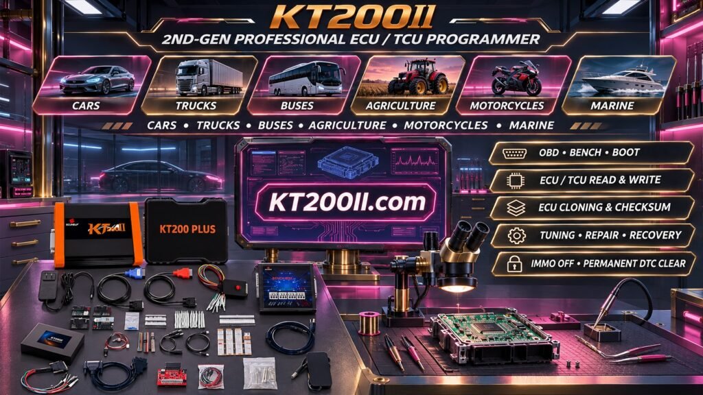
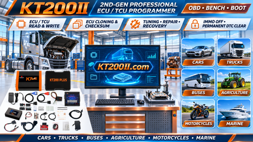
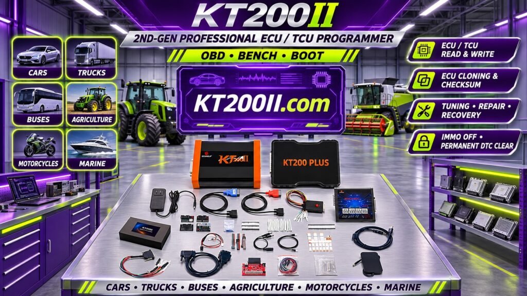
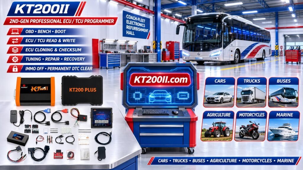
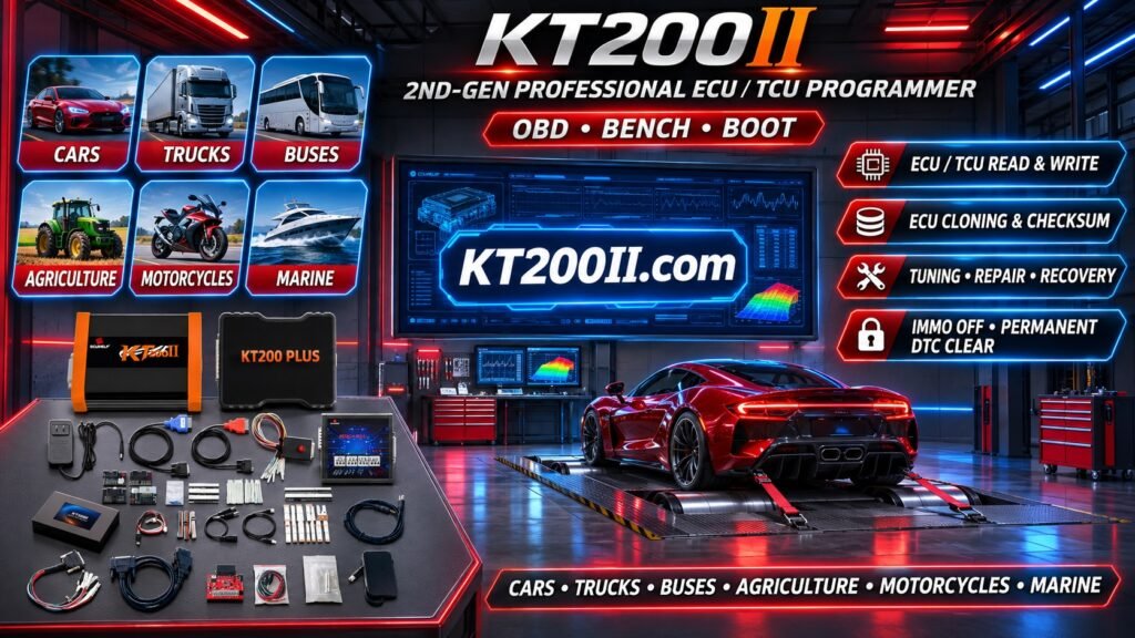
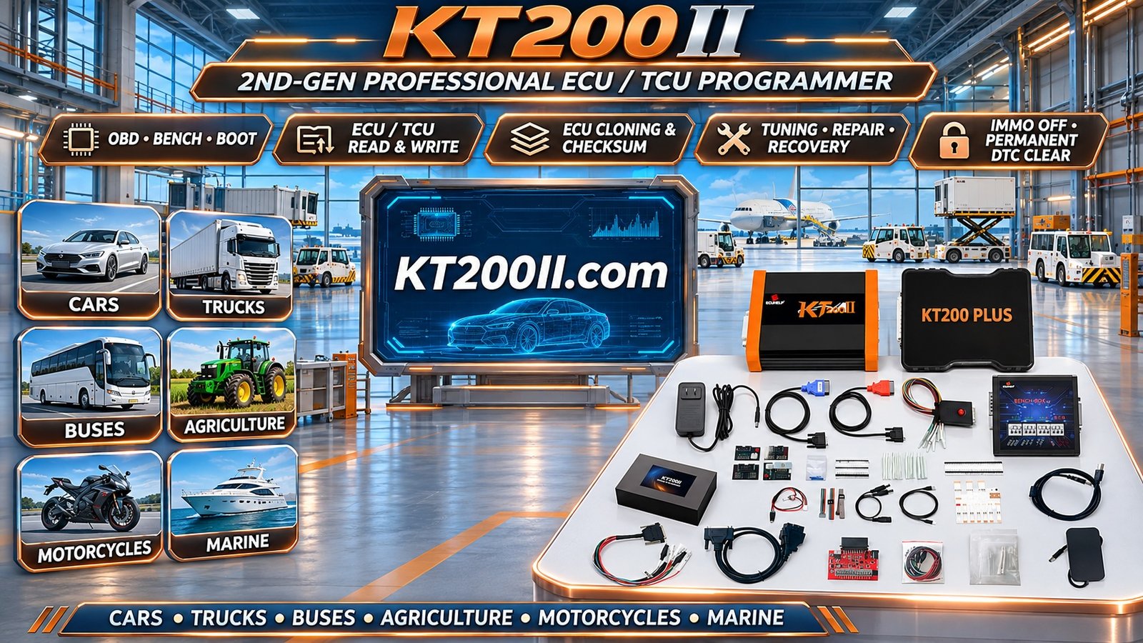
KT200II is an automotive ECU and TCU programming tool designed for professional automotive electronics applications.
Depending on the supported transmission controller and available programming protocol, supported workflows may include:
- TCU identification.
- Supported memory reading.
- Supported memory writing.
- Flash backup.
- Selected memory operations.
- Bench programming for compatible controllers.
- Other supported programming procedures.
Actual support depends on the exact transmission model, TCU hardware number, processor architecture and software version.
Support for one transmission family does not automatically guarantee compatibility with every controller in that family.
Before purchasing or starting a programming operation, technicians should verify the exact controller against the latest KT200II support information.
For additional information, visit:
- KT200II Product Information
- KT200II Operation Modes
- KT200II Software
- KT200II Support List
- KT200II Technical Support
20. TCU Programming Checklist
Before beginning a TCU programming operation, confirm:
- Vehicle identification recorded.
- Transmission family identified.
- Complete TCU hardware number recorded.
- Software identification checked.
- Processor architecture identified where necessary.
- Memory configuration understood.
- Programming compatibility verified.
- OBD, Bench or Boot method selected.
- Correct wiring diagram obtained.
- Power and ground connections checked.
- Original data backed up where supported.
- Replacement hardware compatibility confirmed.
- Target file compatibility verified.
- Programming completed successfully.
- Required coding and adaptations performed.
- Final transmission diagnostics completed.
Frequently Asked Questions
What is TCU programming?
TCU programming involves reading, writing or transferring supported electronic data in a transmission control module.
Can a TCU be programmed without removing it?
Some transmission controllers support OBD programming while installed in the vehicle. Others require Bench or Boot procedures.
What is the difference between ECU and TCU?
The engine ECU primarily manages engine operation, while the TCU manages transmission functions. Some vehicles integrate both functions into a combined controller.
Can all automatic transmission controllers be cloned?
No. Cloning availability depends on the controller hardware, memory architecture, software and security requirements.
Does TCU reading guarantee successful writing?
No. Reading and writing are separate capabilities and must be verified independently.
Does replacing a TCU require adaptation?
Some transmissions require coding, initialization or adaptation procedures after controller replacement. The exact requirements depend on the manufacturer and transmission model.
Why does a TCU fail to communicate?
Possible causes include missing power, poor grounding, damaged wiring, communication faults, incorrect protocol selection or internal electronic failure.
Does KT200II support every ZF 8HP transmission?
Compatibility must be checked against the exact TCU hardware number and software version. Support for one ZF 8HP controller does not automatically mean support for every 8HP generation.
Conclusion
TCU programming is an important part of modern automotive electronics servicing. Understanding transmission controller architecture, Flash memory, communication protocols and adaptation requirements helps technicians perform accurate diagnostics and supported programming operations.
Before reading or writing a transmission controller, always verify the exact hardware identification, programming protocol, memory configuration and replacement compatibility.
KT200II provides ECU and TCU programming solutions for professional automotive technicians, with available functions depending on the supported controller and software protocol.
Visit KT200II.com to explore product information, operation modes, software resources and the latest support list.